• Welcome Visitor! Please take a few seconds and Register for our forum. Even if you don't want to post, you can still 'Like' and react to posts.

AC Panel Knob Wiring Diagram


So I did what @RonD suggested.

With Key ON, I ran a jump wire from the Negative Terminal to the Orange/Black and it blew air that I couldn't feel unless my hand was in the vent (which is what it's been doing).

With the Key OFF, I unhooked the positive battery terminal, ran a jumper wire from the positive of battery to the orange/black and the blower made a buzzing sound, but that was really it.

I also ran the orange/black wire to other grounds (i.e cigarette lighter, dash frame, etc) and same thing as that the air would blow, but you wouldn't feel it unless the hand is in the vent.

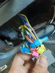
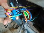
I took a look at the wiring under the dash, and there's a orange/black wire that goes into a connector, but nothing is plugged into it, and since it's with all the other wires that goes through the firewall, I am not sure if it's the same one that goes to the AC Knob.

If I just run a wire from the positive battery terminal with a kill switch (or 2), would there really be any drawbacks from this? Since to my understanding the HIGH setting already does this.
 
You said running 12volt wire did NOT work?????

Are you sure the fan is turning the correct way?
It IS a DC motor so if you reverse the 12v and ground wires it spins backwards
Like power window motors, up and down is just reversing polarity, blower fan is no different

Yes, you can install a switch on the dash but use the GROUND so you just need 1` wire to the fan motor, same as switch does now

Battery negative-----(cab metal)------switch-----------------------------(-)Blower(+)-------------fuse------battery positive

Must have a FUSE, 30amp
 
When the blower doesn't blow much air, you can take your meter while it's still turning, and put your meter across the motor. You will then read what the motor sees. If it's not seeing 12v, then it's not going to blow very hard and you have a problem somewhere. If it does have 2v across it, your problem is something else.

Putting the meter across the motor means one lead of the meter on one motor wire, and the other meter lead on the other motor wire.
 
@RonD With the key off and positive battery terminal disconnected from the battery. I took a jumper wire and ran it from the positive battery terminal to the orange/black wire (I ran the wire from the positive battery terminal to the orange/black wire under the dashboard FYI)
I took a multimeter, and it's getting the 12 V from the battery, but the blower is just making a buzzing sound, it's not blowing air at all, where as with the orange/black wire connected to the negative with the key on, it blew air, but you wouldn't feel it unless your hand is in the vent itself.

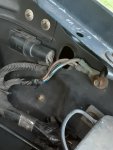
As far as I can tell the blower has a orange/black wire and and a black wire only coming off it. It has a pigtail connector and the plug as that mold that only allows the plug to go in one way.

I apparently had heat exhaustion the last couple of days so I'm relaxing today.

When I was looking at the firewall tracing the wires, I found a orange/black wire with a connector, but nothing plugged in, when I get back to it, I am going to T-Splice that wire and see if it's the same orange/black wire that suppose to go to the blower.

I will do @franklin2 suggest to when I get back to it.
 
Orange/black wire is the NEGATIVE wire, the ground in the cab

There should be a BROWN wire at the blower, thats the Positive

Unplug the blower connector
Turn on the key
Test which wire(truck side) is 12volts, that comes from fuse 9 in the Cab fuse box(30amp), it has power when ever key is on


Does the blower motor have a Red and Black wire?
Or are they the same color?
 
@RonD I see a orange/black and a orange/brown wire going to the blower directly.
I didn't see that before.

The pigtail connector off the blower has a red and black wire.
The truck side of the pigtail is orange/black and brown/orange.

The orange/black goes to the red wire on the blower pigtail
The brown/orange goes to the black wire on the blower pigtail.

I did a ohms/ping test on 3 multimeters and all gave the same results.

brown/orange - black pigtail to negative battery terminal = ~4.4ohms/ding sound
brown/orange - black pigtail to positive battery terminal = 0.0 ohms/ding sound

orange/back - red pigtail to negative battery terminal = ~6.3ohms/ding sound
orange/black - red pigtail to positive battery terminal = 0.0 ohms/ding sound

I will do that test in a few minutes. I have to stop and watch the kids.


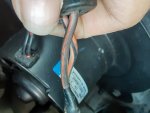
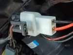
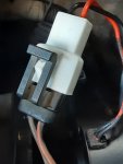
20210803_161038.jpg20210803_161045.jpg20210803_161056.jpg20210803_161140.jpg20210803_161203.jpg20210803_161212.jpg20210803_161221.jpg
 
I tested both wires (orange/black & brown/orange) with a multimeter and they both get 11.90 Volts with the key in the on position.
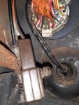
Also picture 3 in the above post is a orange/black connector that doesn't have anything plugged in and I can't trace to see where it goes since it goes into the bundle of wiring.
 
Brown/orange wire should be plugged into the RED wire on blower motor(12v from fuse 9 in cab)

Orange/black wire should be plugged into the BLACK wire, it is the GROUND from resistor block via switch in the cab

The orange/black goes to the red wire on the blower pigtail
The brown/orange goes to the black wire on the blower pigtail.

So with the above the blower is spinning BACKWARDS
 

Attachments

@RonD You are amazing, That fixed it.

I had to put the pigtail in the blower when I bought it and it came with no instructions.
Thank you for helping me with this.
Where are the diagrams that you and eric provided(on my other post)?
I didn't see those in my chilton repair manual and I couldn't find them on the internet.
 
Good work (y)

I get mine from local Library website, they have an Auto Repair section

Need to get Library card and set up a PIN to log in, and its all free :)
Well not really free if you paid your taxes, lol

They have ALOT of wiring diagrams for almost any vehicle, and repair manuals as well
You can print or save them as PDFs
 
@RonD if I can ask one more question, since AC is my next project on this truck.
The previous owner had the AC ripped out, so I gota get the AC line and whatever connects to the evaporator installed, but I do not know what that part is (that's probably another post).

On the knob, you would push it in to trigger AC, could you help me with with wire that controls?
It would save me some time from doing trial and error if you can.
 
Its just a Key on 12v wire to button, then when button is ON that 12v goes to the Pressure switch and out of pressure switch to the AC Clutch which turns on and engages the compressor
So almost no wiring to speak of

The pressure switch or switches, prevent the 12v from turning on compressor if fluid is low(burn out compressor) or pressure is too high(blow out lines/connections)

The part that is usually next to the evaporator and the heater box is the Receiver/drier aka Accumulator, it stores the compressed "freon" until it can be released into evaporator
It allows AC to work at any RPM of compressor

AC wiring below
12v from fuse 7, key on 12v
Runs to switch on dash, if you get a stock AC panel, Defrost can also power up AC to dry the air in the cab
From the panel the wire runs thru firewall to pressure switch
out of pressure switch to WOT relay, you don't need this unless you want it and Computer(EEC) has the software to use it
From WOT 12v runs to AC Clutch

Fuse--------AC switch----------------pressure switch---------(WOT relay)------------AC clutch----ground


WOT(wide open throttle) relay allows computer to turn OFF AC compressor when driver presses gas pedal down to the floor, this gives driver all available power to pass or ???
When gas pedal comes up AC comes back on
As said its not "part of AC system", so not needed, its part of engine control system
 

Attachments

@RonD I'll have to do some additional research. I understand what you're saying but honestly I am not sure how that works lol.
I'm not a mechnical engineer so the pressure switch functions sometimes gets over my head.

If there isn't a wire that sends the signal to the AC Compressor of when the switch is in "ON" or "OFF" then what's the point is the pressure switch to activate the AC? How does the system know when the pressure switch is activated? I'm assuming that is the part that you call the WOT but again, how does the indication of what position the pressure switch is in gets to the WOT if it's not by a wire?

That's what my brain is trying to understand with my own independent research, but with me being sick (COVID) I honestly haven't had time to do anything besides bed rest.
 
Any automotive relay needs 12volt and a ground to activate, remove either one and relay doesn't activate

Same for a 12volt light bulb, you can give the bulb 12volts on one, or BOTH, terminals and nothing happens
Until you also ground it, no voltage can FLOW THRU the bulb which is what causes it to light up, until it has 12v(positive battery terminal) AND a ground(negative battery terminal)

A Relay needs the same FLOW thru it's "coil" to activate

In your year the AC clutch relay gets 12volts with key on, but has no Ground, so stays off

Pressure switches have 2 contacts inside that are connected unless pressure is too high or too low depending on the switch design

Pressure switch wire is Grounded at one end, then runs from switch to switch so is a GROUND at the other end unless a switch opens, cutting the ground

This Ground is used to activate the AC Clutch relay, which activates the Compressor

If a pressure switch should open AC clutch relay would turn off, saving the compressor from burning out, low pressure, or an AC line from BLOWING OUT if pressure was too high
So a safety thing

In your year Ford put the PCM(engine computer) in the mix, it has an internal relay that connects the pressure switch ground to the AC clutch relay, activating it

So the pressure switch wire runs to the PCM not the AC Clutch relay, and another wire runs from PCM to AC clutch relay's ground

When you select AC on the cab control panel that signal goes to the PCM, and PCM activates it's internal relay, connecting pressure switch ground to AC Clutch relay's ground terminal, since it already has 12volts it activates
 

Sponsored Ad


Sponsored Ad

TRS Events

Member & Vendor Upgrades

For a small yearly donation, you can support this forum and receive a 'Supporting Member' banner, or become a 'Supporting Vendor' and promote your products here. Click the banner to find out how.

Recently Featured

Want to see your truck here? Share your photos and details in the forum.

Ranger Adventure Video

TRS Merchandise

Follow TRS On Instagram

TRS Sponsors


Sponsored Ad


Sponsored Ad


Amazon Deals

Sponsored Ad

Back
Top