
Why A Doubler
Doublers are typically used by rock crawlers running large tires. As tires get larger, more gear reduction is required to provide enough torque at low speed to turn them. Changing differential gear ratios provides more reduction, but Ford Ranger axles are generally limited to around 5.13 gears (5.38 gears in half ton and one-ton axles) before the pinion gets too small and weak. A doubler multiplies the torque being sent to the tires giving the truck the power it needs to turn them, and the added gear reduction allows the truck to ‘crawl’ at a lower controlled speed over the obstacles.
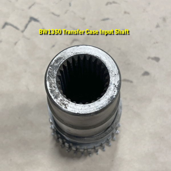
A Ford Ranger dual transfer case (or “doubler”) is typically built using a BW1350 as the front reduction case and a BW1354 as the rear (main) case because of the specific design and parts availability of the manual-shift BW1350, which is adapted to serve solely as a reduction unit. While it is possible to use two BW1354s, the electric-shift versions present specific challenges.
Why BW1350 (front) And BW1354 (rear)?
The common practice of using a manual-shift BW1350 for the front reduction box (the first case in the drivetrain, attached to the transmission) and a BW1354 as the rear (second) case is based on the following:
Design for Modification: The BW1350’s internal design, specifically the way its planetary gear set, and shift mechanism are configured, makes it relatively easy to modify into a compact reduction box (often called a “doubler”).
Adapter Kit Compatibility: Aftermarket doubler kits (like Duffy’s or others) were historically developed around the manual-shift BW1350’s components for the front case. The kits include necessary adapter plates and a custom splined shaft to couple the output of the front case (BW1350) to the input of the rear case (BW1354).
Availability of the Rear Case: The BW1354 was widely used in Rangers, Bronco IIs, and Explorers, making them relatively easy to find as the main, operational transfer case.
Can You Use Two BW1354s?
Yes, using two BW1354s for a dual transfer case setup is possible, and custom doublers for this configuration have been developed. However, the front case must be converted to manual shift.
The primary limitation with using two BW1354s is that the front case needs modifications similar to the BW1350 to function purely as a reduction unit (retaining only its low-range gear set) and to adapt it to the rear case. This often requires a custom, one-off adapter shaft, which can be expensive to machine, or a specific kit designed for the purpose.
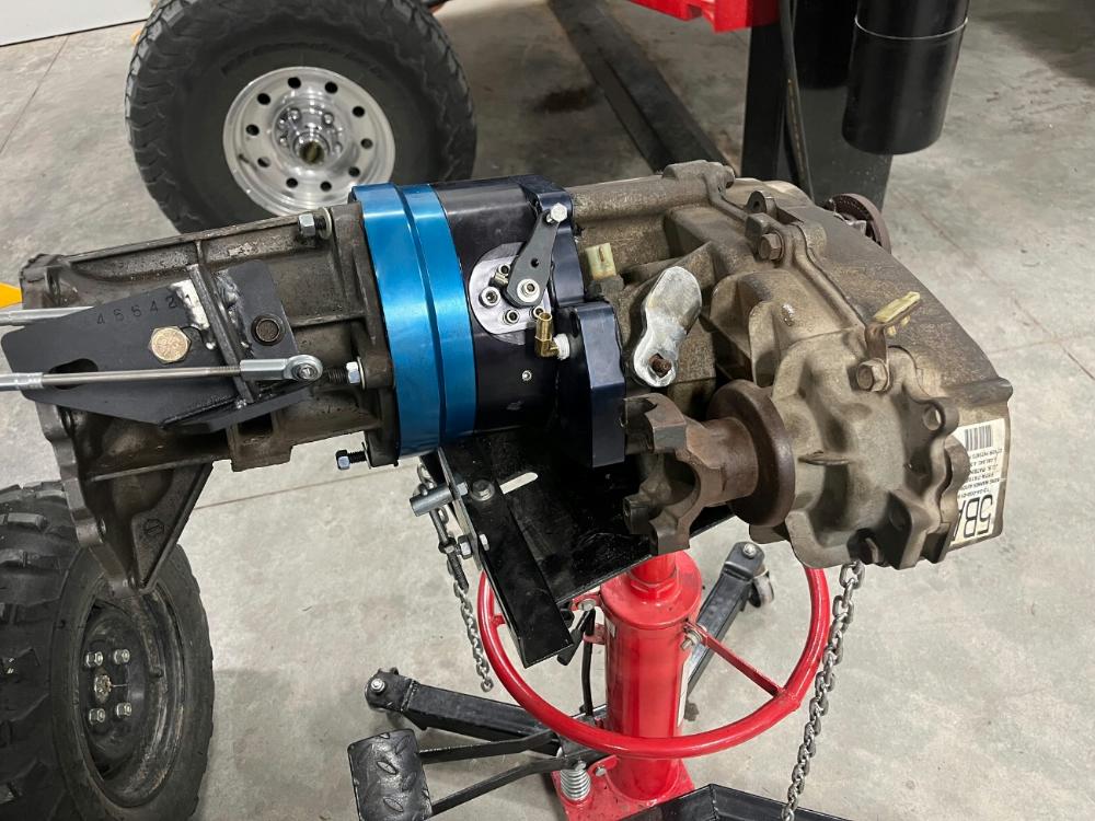
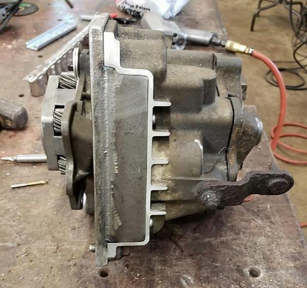
Behemoth Drivetrain makes a ‘Strongbox’ doubler that uses the components from a BW1354 and attaches to the front of another BW1354. The photo at the top of this page is actually a ‘Shorty’ version of the Strongbox attached to a BW1354.
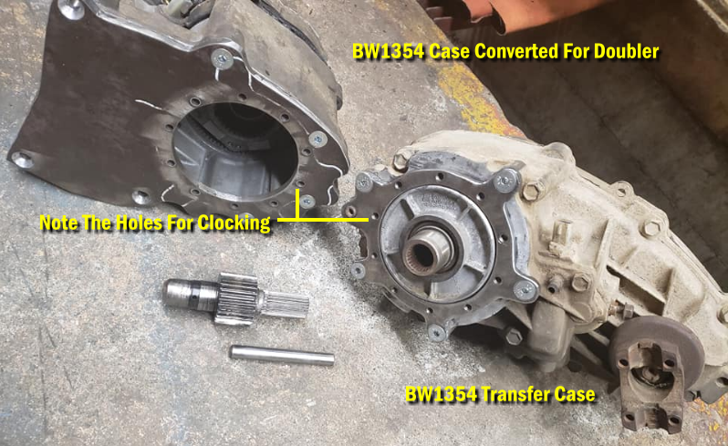
Below is a BW1354 transfer case shell that has been built into a doubler. What I really like is that the person built a clocking ring that attaches to the transfer case, and the doubler bolts to the clocking ring. We’ll discuss ‘clocking’ later.
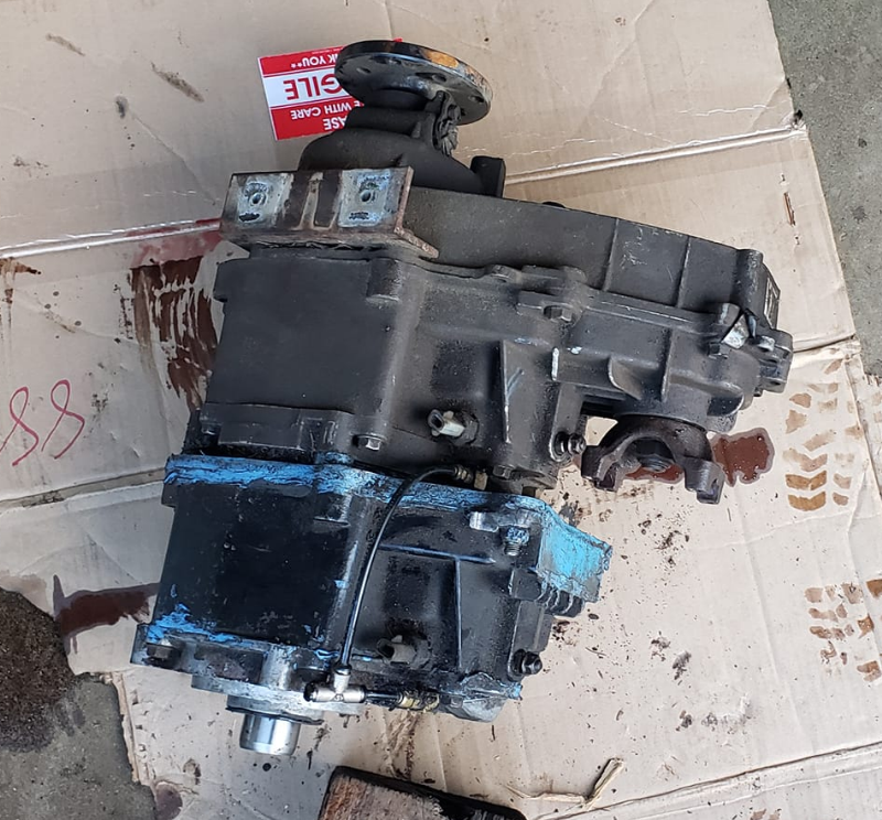
Here’s that same BW1354 doubler mounted to a BW1354 transfer case.
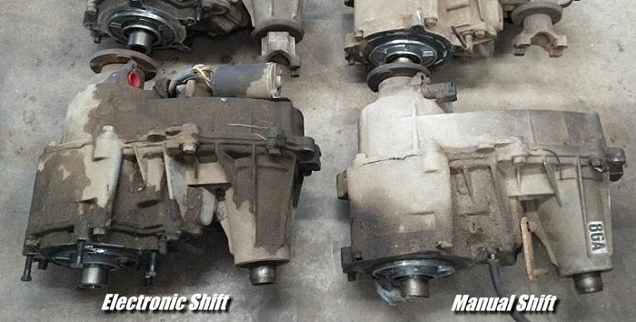
Can You Use An Electric Shift BW1354 For The Main Case?
Yes, you can use an electric shift BW1354 for the main (rear) case in a doubler setup. The electric shift mechanism is an external component; the internal mechanics are the same as a manual shift version (or can be upgraded).
The front case, however, must be a manual shift case. This is because:
The front case is stripped down to just its reduction gears, and the electric shift motor is removed and replaced by the adapter plate and custom linkage/block-off plates.
The electric shifting mechanism is designed to control the main case functions (2Hi, 4Hi, Neutral, 4Lo) in a standard configuration. In a doubler setup, the first case only provides a high/low range, which requires direct, mechanical (manual) control to select the range independently of the second case.
Manual shifters offer reliable, direct mechanical control, which is essential in an off-road “doubler” application where reliable and precise gear selection is critical, and electric motors can fail.
What Is The Low Range Gear Ratio Of The BW1350 & BW1354?
Both the Borg-Warner 1350 and the Borg-Warner 1354 transfer cases used in Ford Rangers have the same low range gear ratio of 2.48:1.
In high range (2H and 4H), both transfer cases operate at a direct 1:1 speed ratio. The 2.48:1 low range ratio provides significant torque multiplication for off-road driving, which is the primary benefit when combining two of these cases into a “doubler” setup, resulting in a crawl ratio of approximately 6.15:1 when both are engaged in low range (2.48 x 2.48 ≈ 6.15).
What Modifications Are Needed For A Manual BW1350 As A Reduction Box
To use a manual BW1350 transfer case as a reduction box (front case) in a doubler setup, it requires significant mechanical modifications, primarily involving disassembly, cutting off the unused part of the case, installing an adapter shaft, and sealing off unneeded openings.
Here Are The Specific Mods:
Case Disassembly and Modification
Complete Teardown: The BW1350 case is completely disassembled, and most internal parts, including the shift forks, chains, and front output shaft assembly, are removed, leaving only the planetary gear set.
Case Shortening (“Stubbing”): The rear half of the BW1350 case is cut down and ground to fit a custom adapter plate. The goal is to retain only the front section that houses the planetary gears.
Block-off Plates: Custom block-off plates (usually included in aftermarket kits) are installed to seal the openings left after removing the unused internal components and shortening the case.
Internal Modifications and Parts
Custom Adapter Shaft: The most critical modification is the installation of a custom, one-piece splined shaft. This shaft goes through the shortened front case, engages the planetary gears, and extends backward to connect the output of the front case to the input of the rear (main) transfer case. This replaces the stock output shaft and chain components.
Modified Shift Rail: The existing shift rail needs to be modified or replaced with a shorter one (often included in a kit) to allow engagement and disengagement of the low range within the newly configured reduction box. A custom shifter linkage is then connected to manually control the “high” (1:1 ratio) and “low” (2.48:1 ratio) ranges of the front box independently of the rear case.
Retaining the Planetary Gear Set: The planetary gear set is the only major internal component from the front case that is retained and reinstalled. It’s cleaned, greased, and carefully placed back into the shortened housing with the new adapter shaft.
External Adjustments
Breather Modification: The stock breather vent location on the front case often interferes with the new adapter plate. The stock vent is usually plugged, and a new vent is drilled and tapped into the case or the adapter plate itself and extended to a high point to prevent fluid leaks and allow the case to breathe.
Adapter Plate Installation: The custom adapter plate is sealed (using gasket material or RTV) and bolted to the modified rear of the BW1350 case.
Driveshaft and Crossmember Modifications: Due to the added length of a second transfer case, modifications to the transmission crossmember and the rear driveshaft (shortening) and front driveshaft (lengthening) are necessary.
These mechanical modifications essentially turn the manual BW1350 into a specialized, manually controlled, 2-speed reduction unit that is physically attached to the input of the second transfer case.
Function of the Adapter Shaft
Power Transfer: The shaft serves as a solid, one-piece connection that replaces the original, individual input and output shafts of the two cases. It must handle all the engine’s torque passing through the front case’s planetary gears and into the second case.
Mechanical Coupling: The shaft is precision-machined with splines on both ends to mate perfectly with the internal components of both cases.
One end engages the planetary gear set inside the modified BW1350 reduction box.
The other end passes through a custom adapter plate and into the input spline sleeve of the BW1354 main transfer case.
Eliminating Weak Links: Off-the-shelf doubler kits typically use a hardened, custom-made shaft to eliminate potential weak points found in trying to join stock shafts. This ensures the entire drivetrain can handle the increased torque created by engaging the low range of both cases simultaneously.
Mechanics of Operation
Input: Power from the transmission’s output shaft enters the front of the modified BW1350 case.
Reduction/Direct Drive: A manual shifter selects either high range (1:1 ratio, power goes straight through) or low range (2.48:1 reduction, power is routed through the planetary gears).
Transfer: The custom adapter shaft receives the power from the front case’s output (either direct or reduced speed) and physically rotates the input of the rear BW1354 transfer case.
Second Stage: The rear BW1354 then takes that input speed and the driver selects a final output mode (2Hi, 4Hi, Neutral, 4Lo) as normal, directing power to the front and/or rear driveshafts.
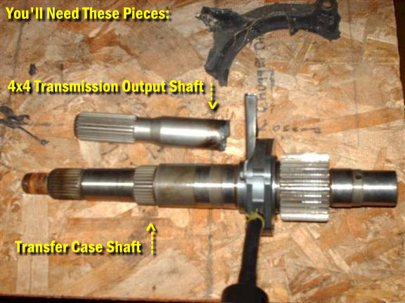
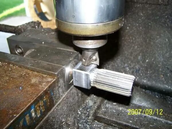
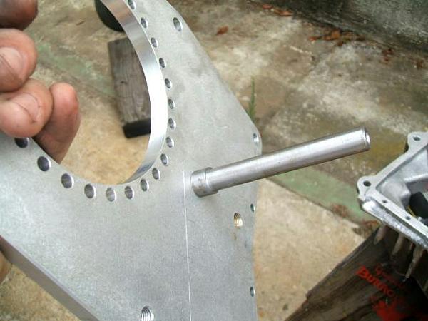
Making An Adapter Shaft
One of the most important parts you’ll need is an output shaft from a 4WD transmission out of a Ford Ranger / Bronco II, early Explorer. You’ll also need the shaft that was in your donor transfer case.
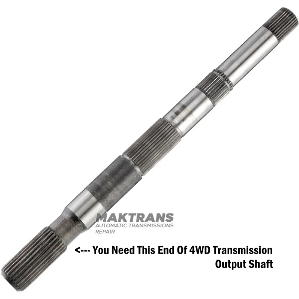
Total output shaft length for a 4WD 4R55E transmission is – 353 mm. You only need the end.
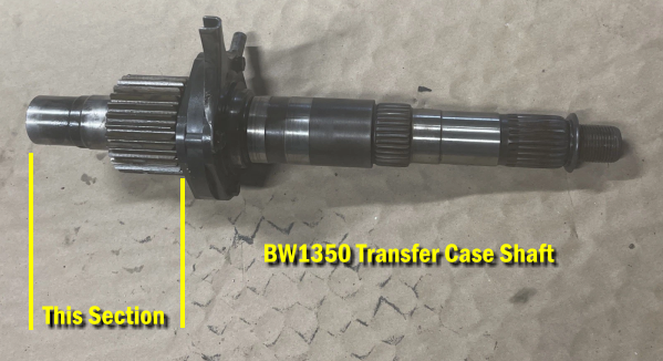
You’ll need this end of the transfer case shaft:
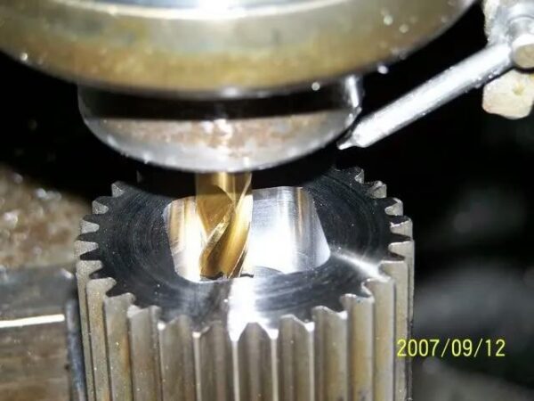
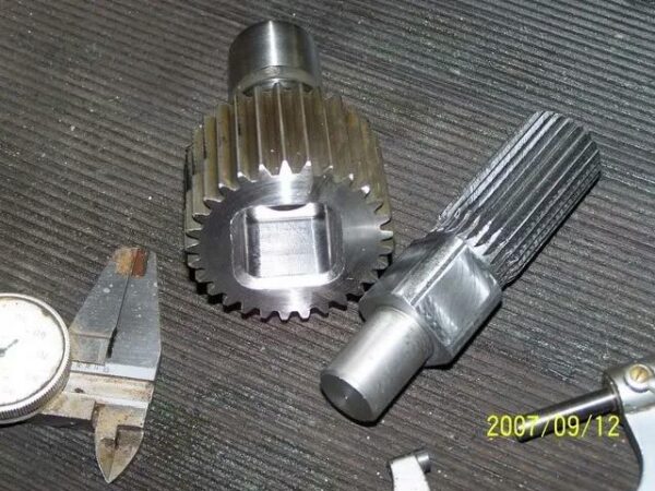
A machine shop will need to bore this opening larger in the transfer case shaft:
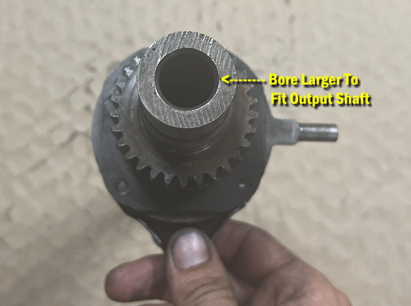
And then lathe down the 4WD transmission output shaft so that it can be pressed into the bore in the main shaft. Then it’s welded together.
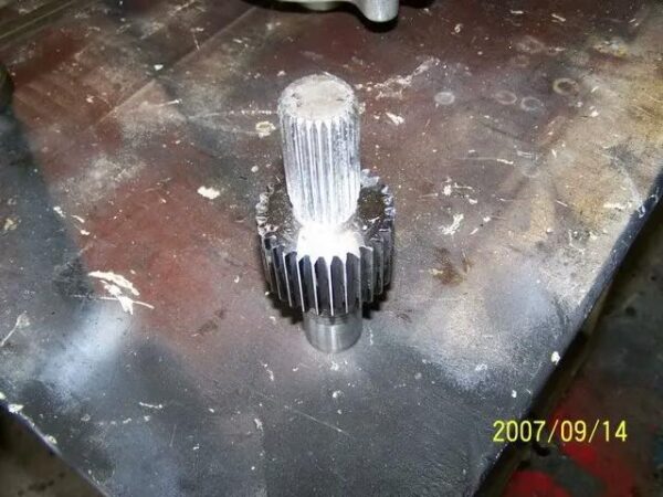
Your final shaft will look like this:
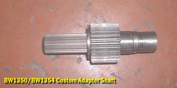
You need to take into consideration the thickness of your adapter plate that sandwiches between the main transfer case and your new doubler and make sure your shaft is built to the proper length so that the 4WD output shaft on this adapter shaft fully reaches and engages the input shaft in your transfer case.
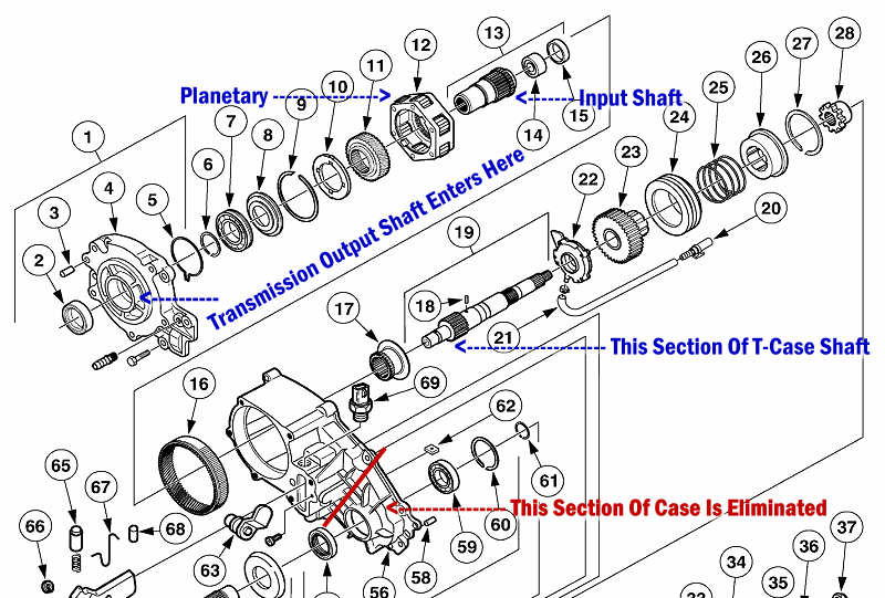
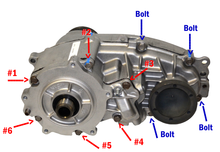
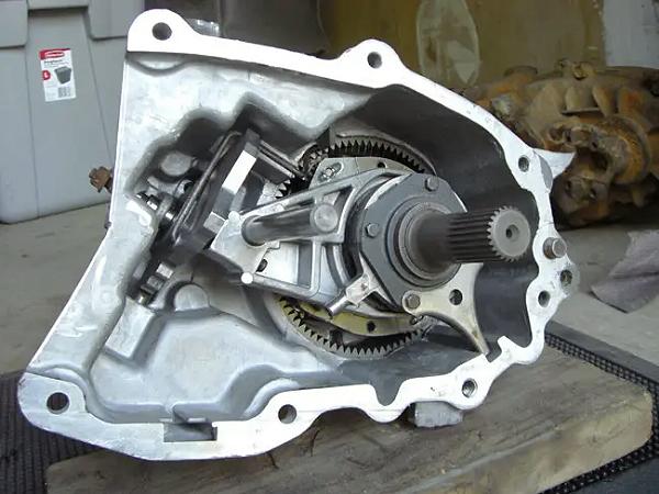
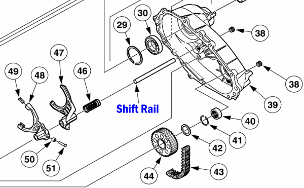
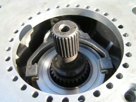
Just to help you visualize this and, here’s an exploded view of a BW1354 transfer case (The BW1350 is similar). The section of the transfer case shaft will have the 4WD transmission output shaft pressed in and welded basically where the ’18’ arrow is in the diagram. Your new doubler consisting of the front half of the case will replace the stock adapter plate (‘4′ in the diagram) and the 4WD transmission output shaft will engage the input shaft (’13’ in the diagram’) in your BW1354 main case.
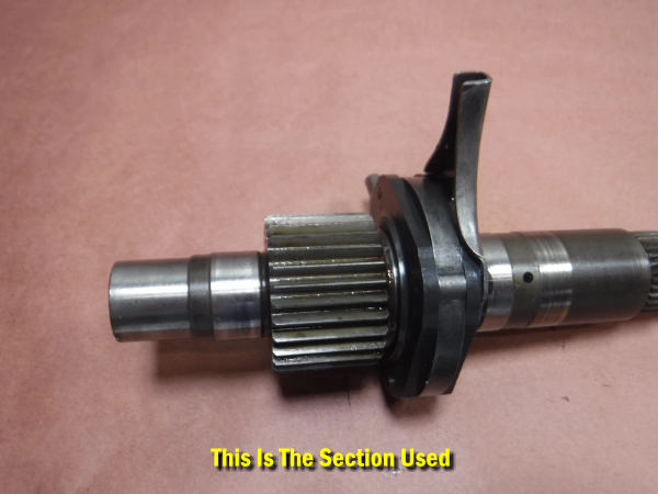
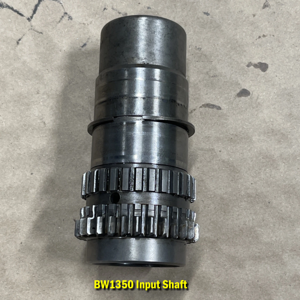
Again, for visual reference, you can see the splines in the BW1350 input shaft. The BW1354 would be the same. You can see how it’s splined to accept the 4WD transmission output shaft.
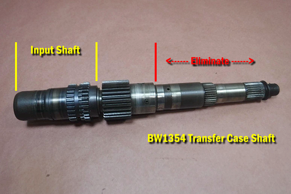
Using a BW1354
You could build a doubler using a BW1354 case as well. It’s the same process. Below is a BW1354 transfer case shaft. This one for some reason has the input shaft with it. You would eliminate the area from the red line out to the right, bore it out, and press in and weld the 4WD transmission output shaft here.
Pump Assembly
Here’s an adapter shaft someone made next to a transfer case shaft. I’m not sure why the pump assembly is still attached. This adapter shaft is actually longer than the one shown above.
When the doubler is reduced to the front half of the case and the adapter plate, the pump assembly, which usually consists of a plastic housing and a gerotor-style pump, no longer fits correctly and interferes with the new configuration and the adapter shaft.
Since the front case is stripped down to just the planetary gears and has no fluid pump or friction clutches (which require the specific friction modifiers found in ATF), some people have used gear oil in the doubler instead of ATF. The thicker gear oil provides better splash lubrication and a thicker film on the metal parts.
Gear oil is significantly thicker than ATF and contains “extreme pressure” (EP) additives designed specifically to protect highly stressed gear teeth and bearings under intense pressure and sliding action, such as those found in a reduction gear set. In a doubler setup, the front case’s planetary gears endure extreme torque loads when both cases are in low range.
Square Bore Adapter Shaft
This person made a square bore adapter shaft.
They started out by machining an output shaft from raw metal instead of using one from a transmission.
Then machined the end square.
And then did a square bore of the transfer case shaft.
This square bore will give it more torque strength. Notice how the bore is tapered so it can be filled with weld.
Welded up and machined smooth.
Common Challenges When Installing A Custom Adapter Shaft
Alignment and Fitment
Spline Engagement: A common challenge is achieving proper spline engagement between the adapter shaft’s splines and the internal gear sets (the front planetary gears and the rear case input sleeve). The fit can be very tight, sometimes requiring significant force or minor filing of the leading edges of the splines to slide together smoothly. Forcing the shaft can damage components.
Bearing Fitment: The adapter plate often houses a new bearing for the shaft. This can be a very precise fit, sometimes requiring the bearing to be heated slightly before installation to allow it to seat properly.
Shaft Depth and Clearance: The depth of the shaft needs to be exact to ensure full engagement without bottoming out or causing stress when the cases are bolted together. Misalignment can lead to vibrations, hard shifting, and premature wear.
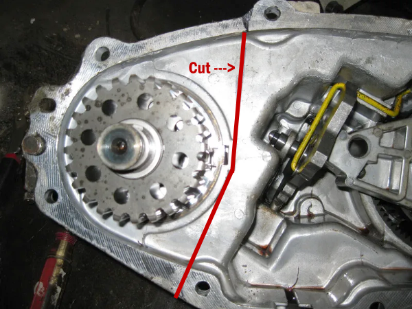
Splitting & Cutting The Case
First remove the bolts that hold the adapter plate on (red) and remove the adapter plate. The planetary and input shaft will come out with it. Then locate and remove the remaining bolts (blue) that hold the front and rear half of the case together and pull it apart.
You’ll have to cut off the unused portion of the case so that it’s not blocking the front driveshaft on the main transfer case.
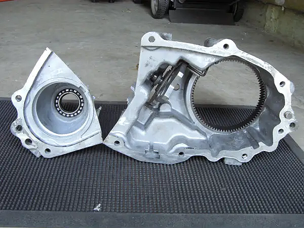
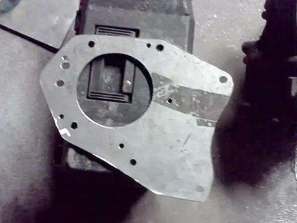
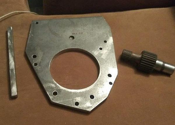
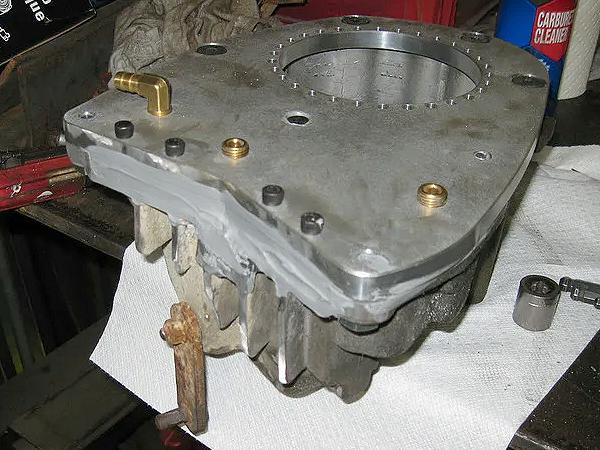
Making An Adapter Plate
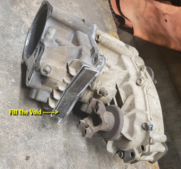
You will have to make a plate for the doubler to bolt on to the rear and enclose the case. This plate will also have to bolt to your main (rear) case to mount the doubler. After cutting the case there will be a gap / void in the side of the case that will need to be filled.
Cutting The Holes
You will need to cut a 5-inch hole in the adapter plate to mount it over the factory adapter plate on your main (rear) transfer case.
Here’s the problem, people guess where the center of the hole is and drill the mounting holes out from there.
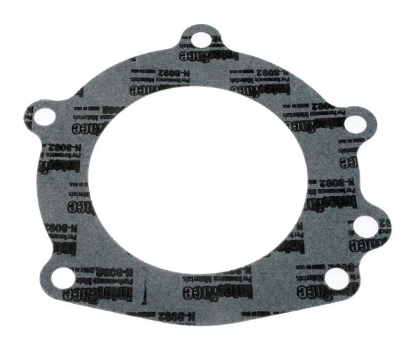
I might suggest that you get a transfer case gasket that fits between the transfer case and the tail housing on your 4WD transmission to use as a template to cut your main hole and the mounting holes around it into your adapter plate. Then bolt your adapter plate to the transfer case. Now set the doubler case over it, mount the factory adapter plate on your doubler that has the planetary with your new adapter shaft, and with the shaft fully engaged into the main (rear) transfer case, it will help you position the case and figure out where to drill your holes to mount the case to the adapter plate.
You would basically be working with a piece that looks like the photo below. You won’t be using the shift rail (rod) because it will be too long and needs to be shortened. By using the output shaft and the alignment dowl pin you’ll be able to align the case to figure out where to drill your holes to mount the case to the adapter plate.
The bolts that hold the adapter plate to the main case will pass from inside the doubler and thread into the main transfer case. The adapter plate will have to be drilled and taped so the doubler case can be bolted to it.
With the case positioned you can then figure out how you’re going to fill the gap in the side of the doubler from where you cut it.
Using All Thread
When TRS forum member 2caseB2 did his Dual Transfer Case Conversion, he drilled all the way through the mounting holes in the factory adapter plate on his doubler and then used all-thread (threaded rod) that passes through those holes and threads into the holes of the factory adapter plate on the front of the main transfer case. Each of the four rods have two nuts, one at the front of the doubler factory adapter plate and one at the front of the rear case factory adapter plate. These four rods and one bolt inside, near the shifter fork area where the chain used to run, holds the doubler together and holds it to the rear transfer case.
His build is the only one I know of to be put together that way. It does however take some of the guess work out of aligning the doubler to the transfer case.
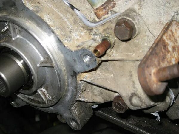
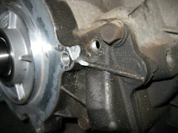
Filling The Gap
I’ve known of this gap being filled two different ways:
1) Weld a piece of aluminum in to fill the gap. The problem with this though is that the case has a very high magnesium content and is hard to weld. TRS Forum Member 2caseB2 noted “I am not a professional aluminum welder, but I had a very hard time getting a good bead between the cast aluminum case and the aluminum plate. I am told this is because of the very high magnesium content in the cast case.”
2) Bolt in a piece of the 1/2″ metal plate cut to fit the gap and seal it with JB Weld.
The two photos above are a BW1354 and the two below are a BW1350. Note that the gap is bigger on a BW1354 than a BW1350.
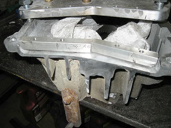
The photo above shows aluminum blocks that were cut to fill the gap and then drilled and tapped so they bolt to the adapter plate.
Below is a photo after the blocks were ground for a better fit and sealed with JB Weld.
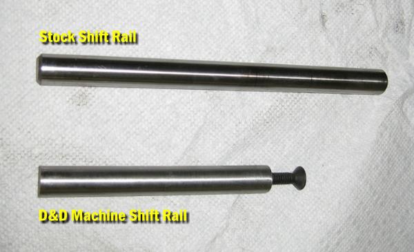
Shift Rail
The shift rail that the shift forks ride on sat in a hole on the back of the case. With the back of the case gone and replaced with a flat plate, the rail is now too long and has nowhere to sit. You will need to drill a hole into the plate, but NOT through the plate for the rail to sit in and then shorten it accordingly.
When D&D Machine made a doubler adapter kit, they drilled a hole through their plate and screwed the shaft in place. I included the photo of their shaft below so you get an idea of how much shorter it will need to be.
Here is a diagram showing the shift rail location for anyone researching this before they actually do start building a doubler.
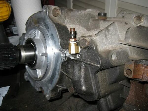
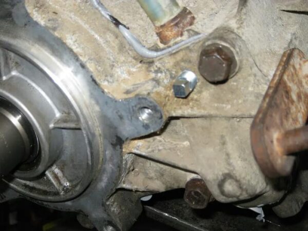
Breather Tube
The transfer case breather tube is on the front of the transfer case. When you add the doubler, it will block the vent tube on your main case.
Remove the stock breather and do a little clearance grinding on the case to enable you to screw a brass 90° elbow in place.
Then grind your 90° elbow to allow it to spin onto the case and stick your old breather vent into the 90° elbow.
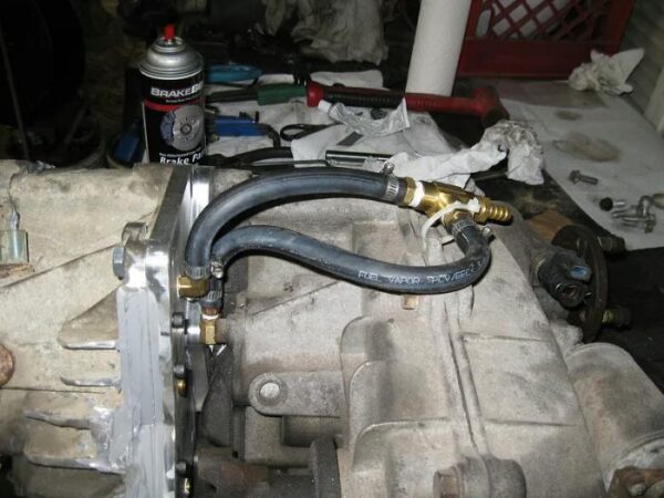
Some people have added a new breather to the rear of the new adapter plate and screwed a plug into the old breather hole.
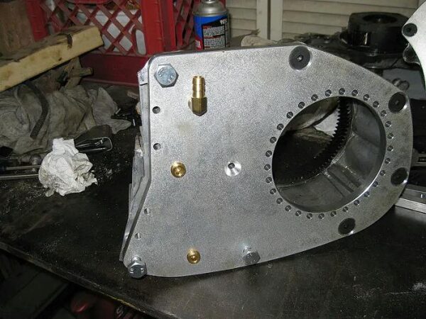
With the hole in the back of the plate near the breather for the rear case, they have used a T-fitting to join the hoses, so they just have one breather hose going up behind their cab or into their bed.
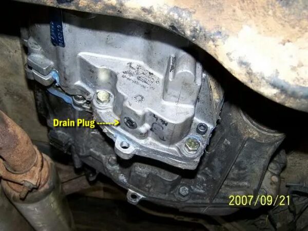
Fill & Drain Plugs
The factory fill and drain holes were located on the back side of the transfer case which is now gone.
Fill Hole – If you relocate the breather as shown above, you can tap the stock breather hole for a fill plug. This will put your fluid level about 1/2 way up the planetary gearset.
Drain Hole – For the drain plug, drill and tap a hole for a 1/4-NPT drain plug in a flat surface as low on the bottom of the doubler as possible.
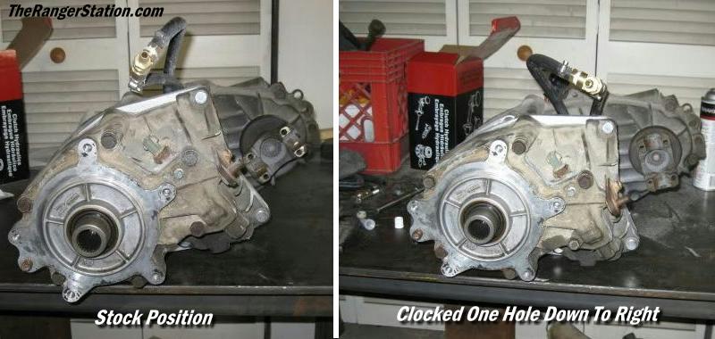
Clocking The Transfer Case
The primary reasons for clocking a transfer case include:
Improving Ground Clearance: By rotating the transfer case upward (closer to the vehicle’s floor pan), the lowest hanging point of the case is raised, improving the vehicle’s “belly” clearance over rocks and obstacles.
Optimizing Driveshaft Angles: When a vehicle is lifted (especially with lifts of 6 inches or more), the angles of the driveshafts become steeper, which can cause vibrations, binding, and premature wear of U-joints or CV joints. Clocking the transfer case helps correct these angles for smoother operation at all speeds.
Component Clearance: Clocking can move the transfer case away from other drivetrain components, such as the transmission pan or exhaust, preventing physical interference.
How it is Done
Clocking is achieved using one of two main methods:
Clocking Rings/Adapter Plates: Aftermarket kits provide a “clocking ring” (an adapter plate with multiple bolt hole patterns) that bolts between the transmission and the transfer case. This ring allows the transfer case to be mounted in various rotational positions (e.g., 10, 20, or 30 degrees from stock). In a dual transfer case setup, the custom adapter plate often includes clocking options.
Drilling New Holes: On some older or specific transfer cases, it’s possible to plug the original mounting holes and drill new ones in the transmission tail housing or adapter to achieve the desired rotation.
It is important to note that while clocking the case upward improves ground clearance, it may require modifications to the transmission tunnel in the floor pan for sufficient room. Conversely, clocking it downward (which is rare) would improve driveshaft angles but decrease ground clearance.
Examples
In the photo below you can see that the person making this doubler made a ‘clocking ring’ that bolts to the main transfer case, and the new adapter plate on the rear of the doubler has small mounting holes that line up with the holes in the mounting ring.
Below, the factory adapter plate on the main (rear) case has had holes drilled and taped into it
Transmission Tunnel, Cab Floor & Fuel Tank Clearance:
Transmission Tunnel Clearance
The added bulk of the two transfer cases may interfere with the vehicle’s floor pan or transmission tunnel, requiring cutting and reshaping (hammering or cutting) for clearance, especially when clocking the cases for better ground clearance.
Fuel Tank Clearance
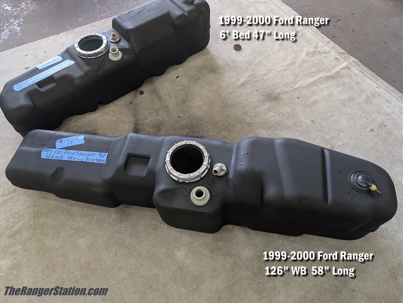
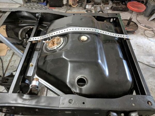
Fuel tank clearance is a big issue when adding a BW1350/BW1354 doubler. The doubler is going to add 6-7 inches to your drivetrain length and push your transfer case further back towards your fuel tank (gas tank).
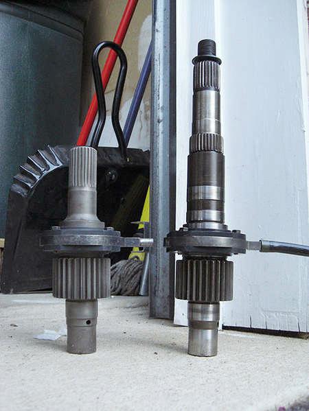
I’ve read that there’s only 4-inches between the transfer case and the fuel tank. That person has a standard cab Ranger, so I crawled under my 1996 Ford Ranger SuperCab and took a look.
It looks like there is 4″ to 4.5″ of space between the fuel tank and my electronic shift transfer case, but without the shift motor (manual case), it looks like there would be about 7-inches of space between the transfer case and fuel tank. So, a doubler may squeeze in there if the rear case is a manual case and not an electronic shift case. I might even be able to modify the mount for the fuel tank and move it back an inch or two.
In the photo below you can clearly see that there is more room behind the manual transfer case on the right than there is behind the electronic shift transfer case on the left.
The 1996 Ford Ranger standard cab came with a standard 17-gallon fuel tank. The 113.9 wheelbase and 3.0L & 4.0L had an available 20-gallon tank option. The 1996 Ford Ranger Supercab all came with a 20.5-gallon tank.
The owner’s manual for 2000 Ford Ranger lists (3) fuel tank capacities:
- Regular cab (Short wheelbase) 16.5-gallons
- Regular cab (Long wheelbase) 20.0-gallons
- SuperCab 19.5-gallons
I found an eBay seller (77radrich_newoldstock4sale) that had a small variety of Ford Ranger fuel tanks listed and actually had the lengths listed for each one.
You can see in the photo below that the 1999-2000 Ford Ranger regular cab short bed (6-foot bed) 16.5-gallon fuel tank is 47-inches and obviously shorter than the 19.5-gallon tank. My 1996 Ford Ranger SuperCab has that 19.5-gallon (or one similar) and I would actually gain 11-inches of clearance with a 16.5-gallon tank at a cost (loss) of 3-gallons.
Ford Bronco II Gas Tank
I know many people have replaced their stock Ford Ranger fuel tank with a Ford Bronco II fuel tank when adding a doubler. This isn’t a bolt in swap. You’ll need to fabricate your own cross member, figure out where your filler neck will come out, and clearance the underside of your bed. A body lift would help provide the clearance you need if you don’t want to trim the underside of your bed.
Mounting and Support: The dual case setup adds significant weight. Over-constraining the assembly with overly stiff mounts can cause the transmission case to crack as the engine and chassis flex. A properly designed crossmember that supports the assembly at a primary balance point with a degree of flexibility is necessary.
Drivetrain Length and Angle
Obviously, adding a second case significantly increases the overall length of the drivetrain. This requires shortening the rear driveshaft and lengthening the front driveshaft. The new length often changes driveshaft angles, which can cause vibrations if not correctly measured and addressed (e.g., proper pinion angle adjustment or the use of double-cardan driveshafts).
Wisdon To Share
From the discussion ‘Building a 1350/1354 doubler- any wisdom to share?‘:
Alignment:
Make sure the two cases are perfectly aligned with each other so the shaft doesn’t fatigue and break prematurely. Make sure it shifts correctly and holds in gear/position.
Planetary gear & Shift Fork (By slammer67):
Basically, my problem was the shifting setup on the BW1350. There was too much play in the shift fork/planetary, and the plastic shift guides would wear down fast causing the doubler to pop out of gear. It left me stranded twice. I started researching and found that you could use the planetary gear and shift fork setup out of the BW1354 in the BW1350.
I haven’t had any more problems since I switched to the BW1354 shift setup. You can use a BW1354 for the doubler, it’s the same setup, but finding a BW1354 manual might be frustrating. You can get a BW1350 manual and an electronic shift BW1354 to rob the planetary and shift setup. 1993 and later BW1354’s have 6-gear planetaries vs 4-gear for the earlier ones. I would suggest switching to the later shift setup. I think my problem came from a leak in the doubler. I didn’t watch it closely enough and the fluid got low and it overheated – which is probably where the excessive wear in my shift fork and planetary came from.
(BW1354 shift fork in BW1350 case – Photo by slammer67)
BW1354 Cases (By slammer67):
Later model (1994+) BW1354’s are a little stronger due to a six-gear planetary and a better shifting setup, but the early ones have the same 4-gear planetary as the BW1350’s
Leaks (By slammer67):
Be careful when you cut the case and weld on a block plate. I think that was one of my leakage problems. I left a small gap that the sealant didn’t fill too well. Some JB Weld and careful filing solved that. I don’t seem to have leaks now, and it’s been a good 6 months since I’ve messed with it.
Breather (By Bray D):
I relocated the breather hose to the top of the case and used the old breather location as a filler hole. This raises the fluid level in the case by a substantial amount. Problem is, it burps fluid out the top of the case, through the relocated breather hose. I’ve got the case out now (replacing slave cylinder in trans), and am having a guy weld a baffle inside the case to hopefully prevent the fluid from getting into the breather hose.
LO Gear Selection (4x4Junkie):
Generally, if you always have the transfer case in LO before you engage the doubler, you should be fine. DON’T EVER run the doubler in LO with the t-case in HI though. This is what tends to break the adapter shafts.
Helpful Discussion In Our Forum:
Kage’s Build Thread – The Lone Ranger – Kage’s ’94 X-Cab Leaf SAS and Bed Bob
Bray D’s Build Thread – Daily Doubler Build
Wisdom To Share – Building a 1350/1354 Doubler- Any Wisdom To Share?
Related Articles:
1983-2011 Ford Ranger Transfer Cases
BW1354 Transfer Case Exploded Parts Diagram
Building a BW1350-1354 Transfer Case Doubler
About The Author
Jim Oaks is the founder of TheRangerStation.com, the longest-running Ford Ranger resource online since 1999. With over 25 years of hands-on experience building and modifying Ford Rangers — including magazine-featured builds like Project Transformer — Jim has become one of the most trusted authorities in the Ford Ranger off-road and enthusiast space.
Since launching TheRangerStation.com, Jim has documented thousands of real-world Ranger builds, technical repairs, drivetrain swaps, suspension modifications, and off-road adventures contributed by owners worldwide. TheRangerStation.com has been referenced in print, video and online by enthusiasts, mechanics, and off-road builders looking for practical, and experience-based information.