
Special Tool(s) / General Equipment:
Lower Arm Ball Joint Separator
Tie Rod End Remover
Removal:
NOTICE: Suspension fasteners are critical parts that affect the performance of vital components and systems. Failure of these fasteners may result in major service expense. Use the same or equivalent parts if replacement is necessary. Do not use a replacement part of lesser quality or substitute design. Tighten fasteners as specified.
NOTE: Removal steps in this procedure may contain installation details.
1. Remove the wheel and tire. Refer to: Wheel and Tire (204-04A Wheels and Tires, Removal and Installation).
2. Remove the front wheel speed sensor. Refer to: Front Wheel Speed Sensor (206-09 Anti-Lock Brake System (ABS) and Stability Control, Removal and Installation).
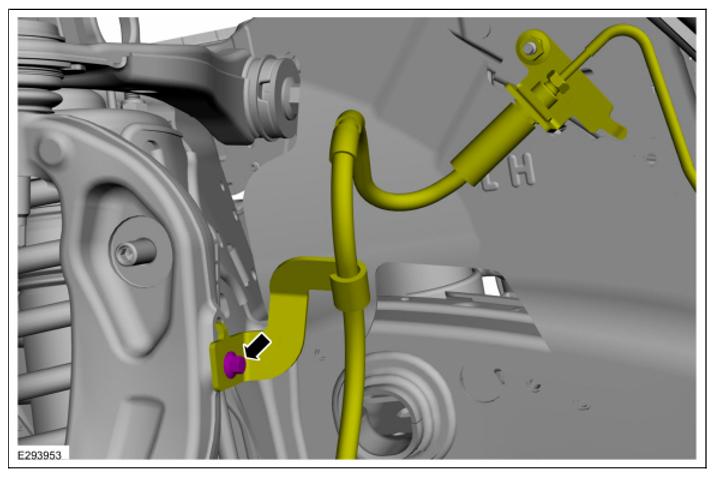
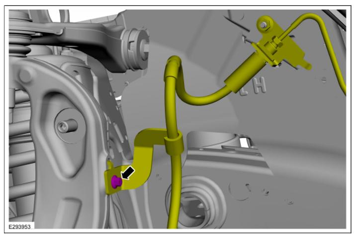
3. Disconnect the brake tube fitting and remove the front brake hose assembly.
4. Remove the brake disc. Refer to: Brake Disc (206-03 Front Disc Brake, Removal and Installation).
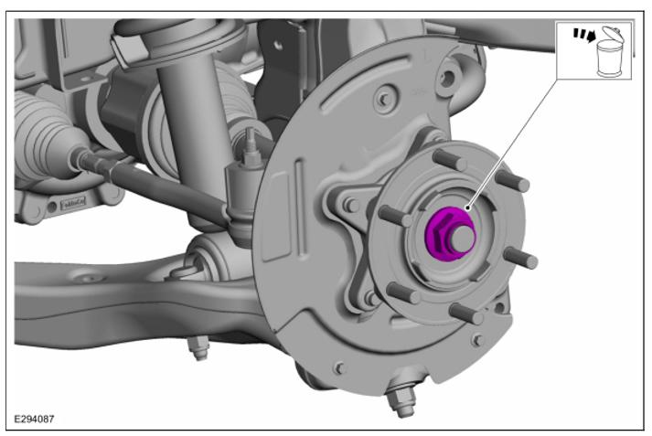
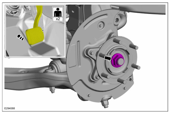
5. Remove and discard the wheel hub nut.
6. NOTE: The stabilizer bar links are designed with low friction ball joints that have a low breakaway torque.
NOTE: Use the hex-holding feature to prevent the stud from turning while removing the nut.
Remove and discard the stabilizer bar link upper nut.
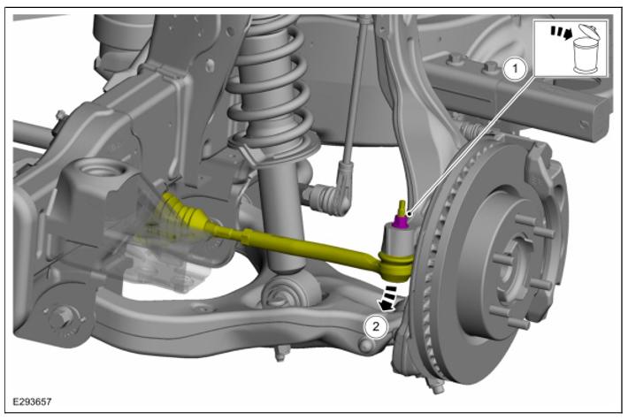
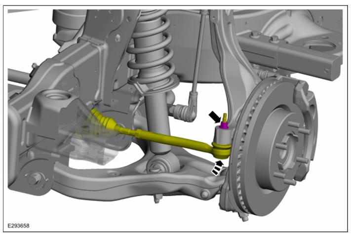
7. NOTICE: Do not use a hammer to separate the outer tie-rod end from the wheel knuckle or damage to the wheel knuckle may result.
NOTICE: Use care when installing the tie rod separator or damage to the outer tie-rod end boot may occur.
NOTE: Use the hex-holding feature to prevent the stud from turning while removing the nut.
Remove and discard the tie rod end nut and separate the tie rod end from the wheel knuckle. Use the General Equipment: Tie Rod End Remover
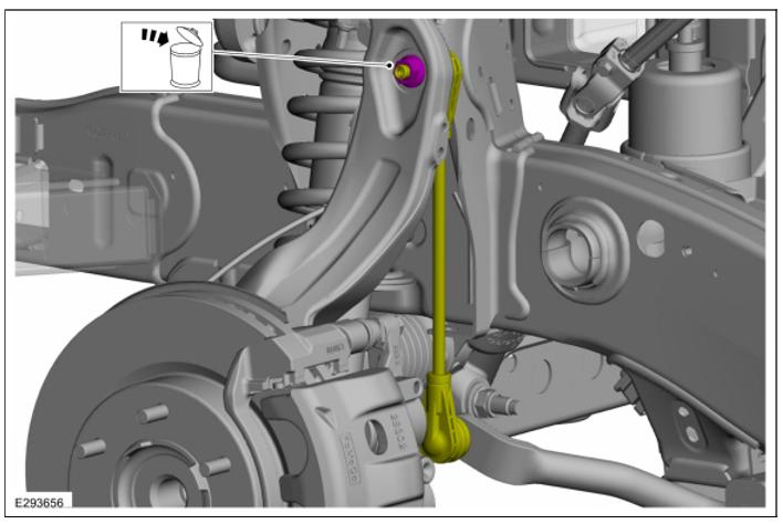
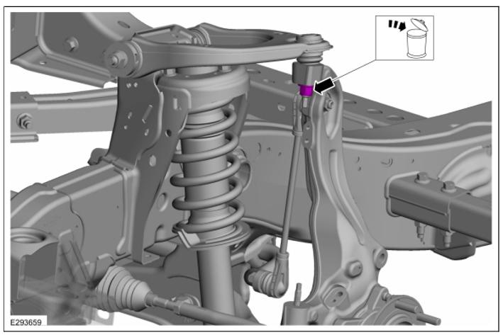
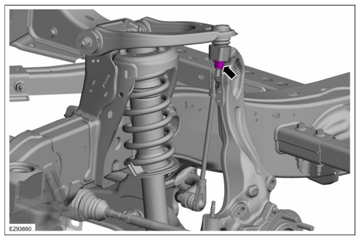
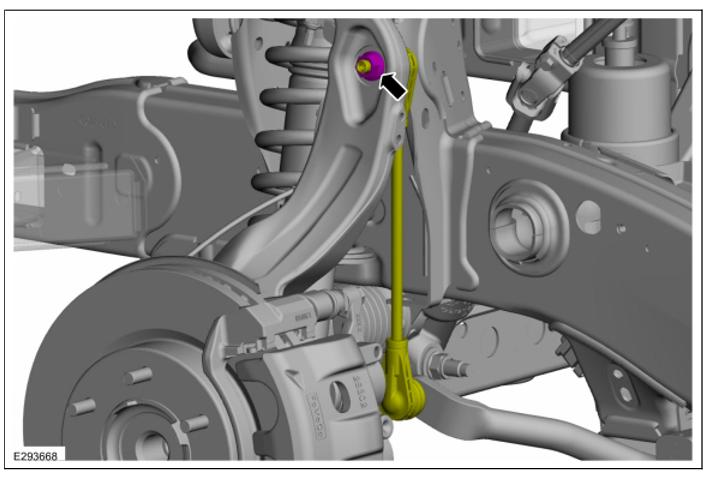
8. Remove and discard the upper arm ball joint nut.
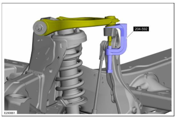
9. NOTE: Be sure not to damage the ball joint boot when installing the Ball Joint Separator.
Separate the upper ball joint from the wheel knuckle. Use Special Service Tool: 204-592 Separator, Lower Arm Ball Joint.
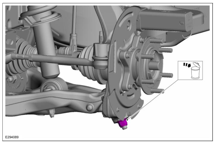
10. Remove and discard the lower ball joint nut.
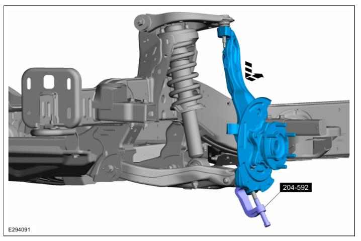
11. NOTICE: Do not use a prying device or separator fork between the ball joint and the wheel knuckle. Damage to the ball joint or ball joint seal may result.
NOTICE: Use care when releasing the lower arm and wheel knuckle into the resting position or damage to the ball joint seal may occur.
Separate the wheel knuckle from the lower ball joint and remove the wheel knuckle. Use Special Service Tool: 204-592 Separator, Lower Arm Ball Joint.
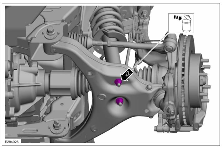
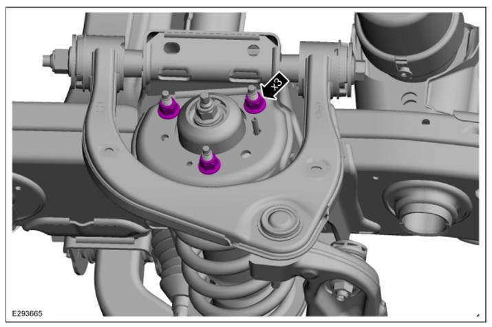
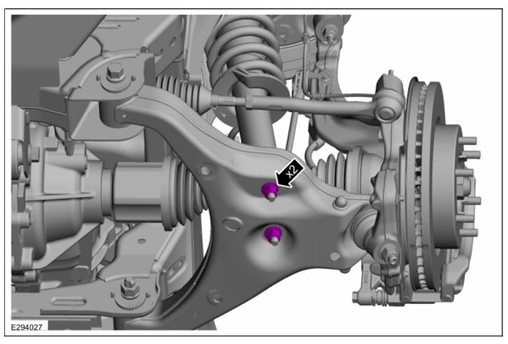
12. Remove and discard the shock absorber and spring assembly lower nuts.
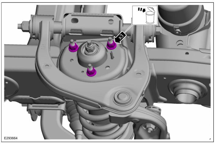
13. Remove and discard the shock absorber and spring assembly upper nuts.
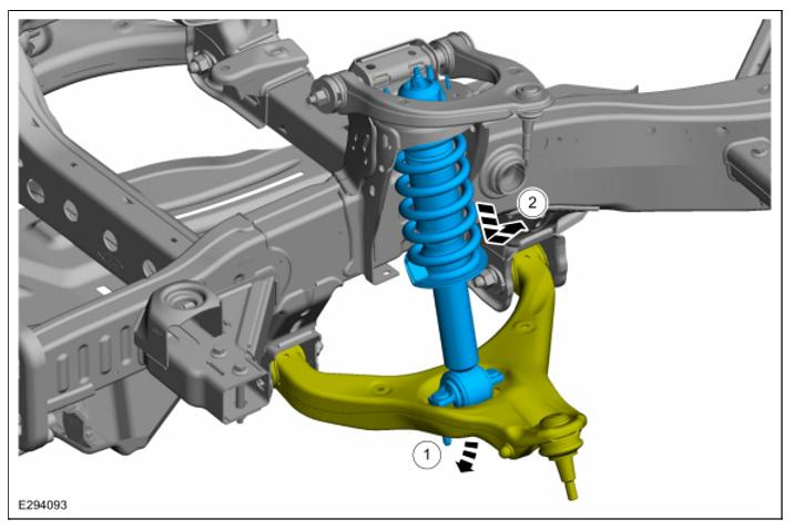
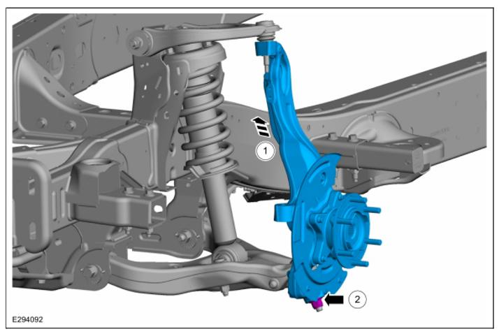
14. Position the lower arm down to gain clearance for removing the shock absorber and spring assembly. Remove the shock absorber and spring assembly.
Installation:
NOTICE: All suspension bushings, including stab bar bushings, must be tightened with the suspension at the normal use ride height (suspension compressed with vehicle weight).
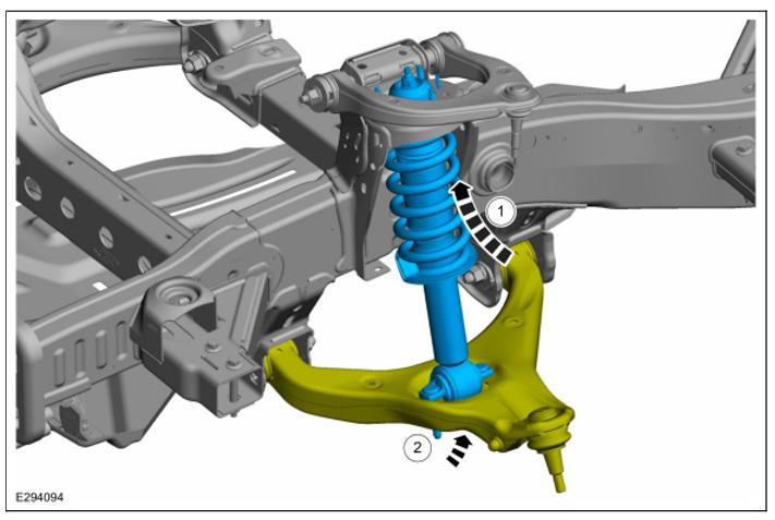
1. Install the shock absorber and spring assembly. Position the lower arm up.
2. Install the new shock absorber and spring assembly upper nuts.
Torque: 41 lb.ft (55 Nm)
3. Install the new shock absorber and spring assembly lower nuts.
Torque: 66 lb.ft (90 Nm)
4. Install the wheel knuckle. Install the new lower ball joint nut.
Torque: 76 lb.ft (103 Nm)
5. Install the new upper ball joint nut.
Torque: 46 lb.ft (63 Nm)
6. Position the brake hose and install the brake hose bracket bolt.
Torque: 159 lb.in (18 Nm)
7. NOTE: Use the hex-holding feature to prevent the stud from turning while installing the nut. Install the new front stabilizer link upper nut.
Torque: 85 lb.ft (115 Nm)
8. Position the tie rod end and install the new tie rod end nut.
Torque: 35 lb.ft (48 Nm)
9. NOTICE: Install and tighten the new wheel hub nut to specification in a continuous rotation. Always install a new wheel hub nut after loosening or when not tightened to specification in a continuous rotation or damage to the components may occur.
NOTE: Apply the brake to keep the halfshaft from rotating. While an assistant applies the brake, install the new wheel hub nut.
Torque: 221 lb.ft (300 Nm)
10. Install the brake disc.
11. Install the front wheel speed sensor.
12. Install the wheel and tire. Refer to: Wheel and Tire.
13. Check and if necessary adjust front camber.
14. Check and if necessary adjust front toe.