2019 FORD RANGER 2WD/4WD EXT/CREW CAB 4” – 6” REAR AXLE FLIP-KIT
BELLTECH 6530 / 6531 FLIP KIT
Download: Belltech 6530 / 6531 Flip Kit Instructions (.pdf)
NOTE: REQUIRES EXHAUST MODIFCATION FOR 4” SETUP
Thank you for being selective enough to choose our high quality BELLTECH PRODUCT. We have spent many hours developing our line of products so that you will receive maximum performance with minimum difficulty during installation Note: Confirm that all of the hardware listed in the parts list is in the kit. Do not begin installation if any part is missing. Read the instructions thoroughly before beginning this installation.
Warning: DO NOT work under a vehicle supported by only a jack. Place support stands securely under the vehicle in the manufacturer’s specified locations unless otherwise instructed.
Warning: DO NOT drive vehicle until all work has been completed and checked. Torque all hardware to values specified.
Reminder: Proper use of safety equipment and eye/face/hand protection is absolutely necessary when using these tools to perform procedures!
Note: It is very helpful to have an assistant available during installation. Some provided images my show addition holes / hardware, if instructions do not reference discrepancies please continue with the provided steps.
RECOMMENDED TOOLS:
• Properly rated floor jack and four (4) support stands
• Safety Glasses
• Wheel chocks
• Grinder equipped with abrasive cut-off wheel/ reciprocating saw
• 1/2” drive torque wrench
• Standard and Metric socket wrench set
• Standard and Metric wrench set
• Tape measure
• Medium weight ball peen hammer
• Marking pen
Difficulty: 3 out of 5 wrenches
Installation Time: 4-6 Hours + alignment
KIT INSTALLATION
As this is a relatively involved installation, WE RECOMMEND that a qualified mechanic, at a properly equipped facility, perform such installation. WE RECOMMEND that the installation be performed on a firm, flat and level surface such as seasoned asphalt or concrete.
The use of safe, and proper equipment, is very important!
!SAFTEY REMINDER!
Check for safe and vehicle stability before proceeding under the vehicle to the begin the following procedures. Never work under a vehicle supported by ONLY a jack. Always use properly rated support stands to support the vehicle.
KIT PREPERATION
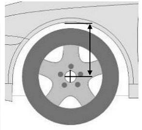
a) Before beginning the install process, measure the hub to fender heights for your vehicle so you can compare the resulting height to the original. Measure vertically from the center of the wheel to the inner edge of the fender. Record the results here:
LF:____________ RF:____________
LR:____________ RR:____________
1) JACKING, SUPPORTING AND PREPARING THE VEHICLE
a) Block the front wheels of the vehicle with appropriate wheel chocks. Make sure the vehicle’s transmission is in “PARK” (automatic) or 1st gear (manual). Activate the parking brake.
b) Loosen, but DO NOT REMOVE the rear wheel lug nuts.
c) Lift the rear of the vehicle off the ground using properly rated floor jack. Lift the vehicle so that the rear tires are approximately 6-8 inches off the ground surface.
d) Lower the vehicle onto the stands slowly and check for possible interference with any brake lines, wire and or cables.
e) Place support stands under each side of the axle to support the weight of the axle. Make sure these are only support the weight of the axle and allowing the 4 other support stands to support the frame.
f) Remove the rear wheels.
KIT INSTALLATION
As this is a relatively involved installation, WE RECOMMEND that a qualified mechanic, at a properly equipped facility, perform such installation. WE RECOMMEND that the installation be performed on a firm, flat and level surface such as seasoned asphalt or concrete.
The use of safe, and proper equipment, is very important!
!SAFTEY REMINDER!
Check for safe and vehicle stability before proceeding under the vehicle to the begin the following procedures. Never work under a vehicle supported by ONLY a jack. Always use properly rated support stands to support the vehicle.
2) DISASSEMBLY
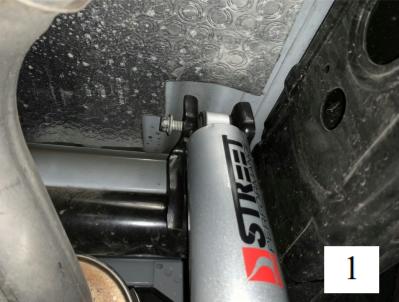
a) Remove both rear Shocks. (Pic 1)
WARNING: Leaf springs may be under tension. Springs under tension store a great amount of energy. Use caution during the following steps to avoid personal injury and/or damage to the vehicle. Be careful not to damage brake hoses and or driveline while relocating rear axle.
b) Properly support the axle using a jack or lifting device so that it can be raised and lowered. Support the rear axle U-Joint to keep the axle from rotating.
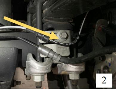
c) Remove the 4 bolts from the rear brake lines attached to axle (Pic 2)
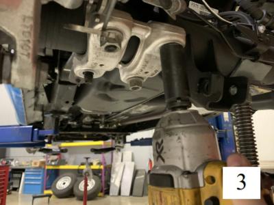
d) Remove the U-bolts nuts and U-bolts. (Pic 3)
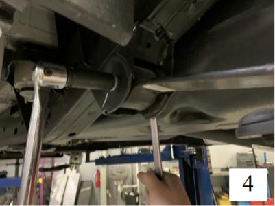
e) Remove the front leaf spring bolt/ nut. (Pic 4)
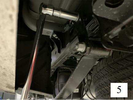
f) Loosen the shackle bolt/ nut at the rear leaf spring; remove the bolt connecting the shackle to the frame. (Pic 5)
g) Remove both leaf springs from under the vehicle. It may be necessary to lower the axle before they can be removed. Be careful to not damage any brake or ABS lines during removal.
h) Remove OEM bump stop and save the bolt as we will reuse this later.
3) LEAF SPRING PREPERATION
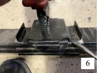
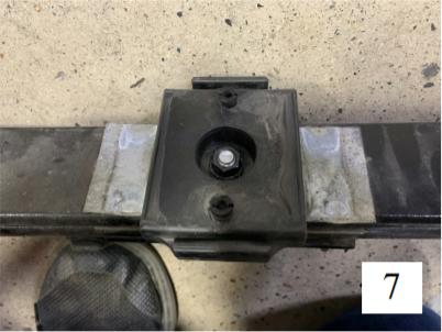
a) Remove the top OEM U-Bolt plate using some pliers to crimp the plastic retainers and flat head screw driver to remove the plate. make sure to not use excessive force. (Pic 6) This will expose the bottom nut. (Pic 7)
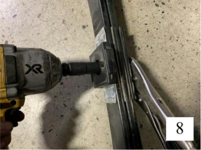
b) Remove the centering bolt by using a pair of vise grips and a impact driver and socket. (Pic 8)
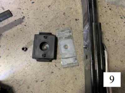
c) Remove the block and upper shim. (Pic 9)
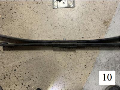
d) With the items removed, flip the centering bolt and tighten back with impact driver (Pic 10)
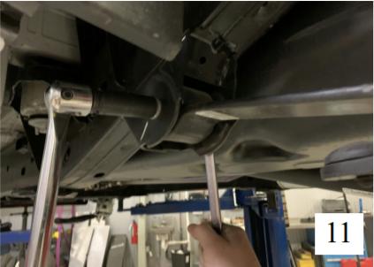
e) Raise the rear axle high enough to clear the leaf spring underneath and install the front of the leaf spring on to the frame. (Pic 11)
NOTE: Having a second person assist when installing the leaf springs is very useful.
4) SHACKLE PREPERATION/ INSTALLATION
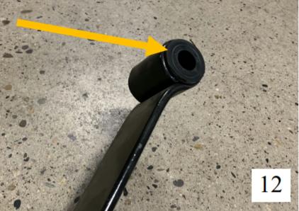
a) Install the OEM rubber bushings for the shackle onto the leaf spring. (Pic 12)
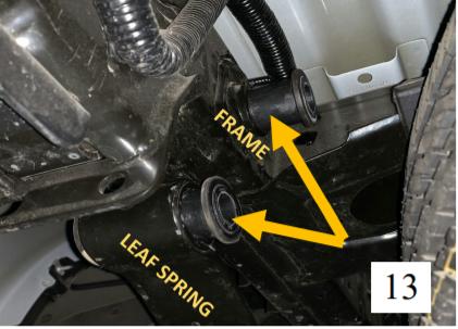
b) Install the OEM rubber bushings for the shackle on the FRAME (Pic 13)
c) Insert the supplied BELLTECH bushing sleeves into the bushings on the frame and leaf spring.
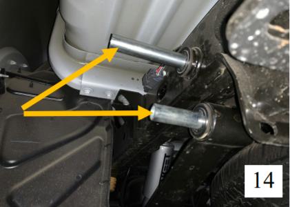
Note: The two different sizes fit accordingly (Pic 14)
4) SHACKLE PREPERATION/ INSTALLATION
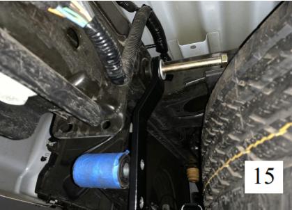
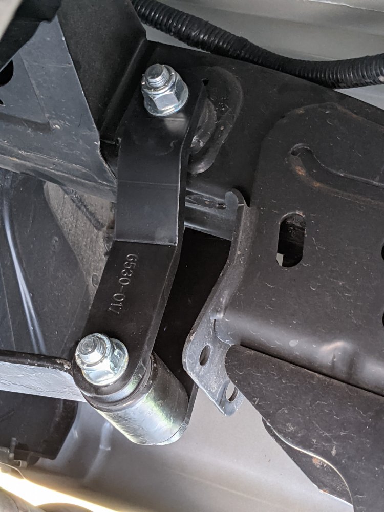
d) Install the BELLTECH INSIDE shackle plate # 6530-017 ( BELLTECH STAMP toward center of truck ) and using the supplied 9/16” X 6” bolt w/ washer to attach at the frame point. (PIC 15)
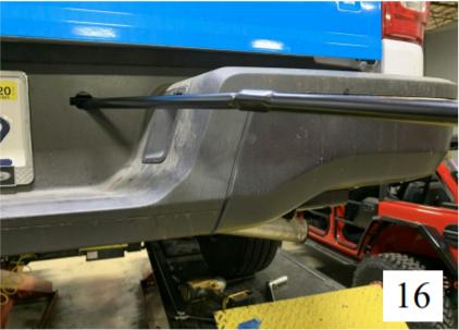
e) Lower the spare tire enough to allow the bottom bolt to be installed, using the OEM supplied kit to lower the spare tire. ( Refer to manufacture hand book for more details) (PIC 16)
NOTE: Two hole adjustment available. For a 5” drop use the top hole, closest to the frame, for 4” drop use the bottom hole, furthest from. For a 6” drop USE the OEM shackle. For a 4” setup skip to step 8a and then return to this section.
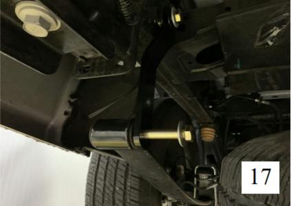
f) Install the supplied 9/16” x 4.5” bolt w/washers to the bottom hole connecting to the leaf spring. (PIC 17)
g) Install the BELLTECH OUTSIDE shackle plate # 6530-015 and tighten both the top and bottom bolts with the supplied 9/16” nut and washer
!DO NOT TORQUE/TIGHTEN THE LEAF SPRING BOLTS , FRONT NOR REAR, UNTIL THE VEHICLE IS ON THE GROUND!
5) AXLE SADDLE INSTALLATION
a) Install the BELLTECH SADDLE 6530-020 with the Belltech logo facing the front ( small tab front, large tab rear) centered on the leaf spring centering bolt.
b) Lower the axle onto the saddle until full contact is made. Install the BELLTECH top Spring pad 6530-003 above the axle.
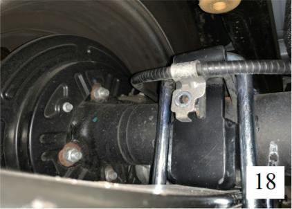
c) Slide the supplied U-bolts ( 6530-007) over the Belltech Spring Pad and going through the axle and Belltech Saddle. (PIC 18)
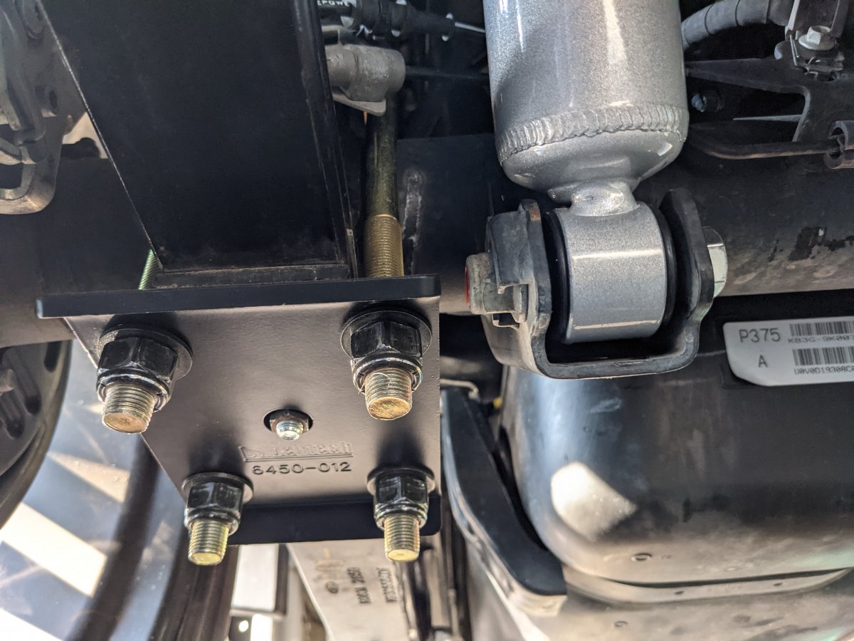
a) Install the BELLTECH U-Bolt Plate 6540-012 inserting the U-Bolts; fastening them using the supplied nuts, 9/16”-18, and washers.
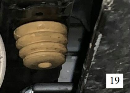
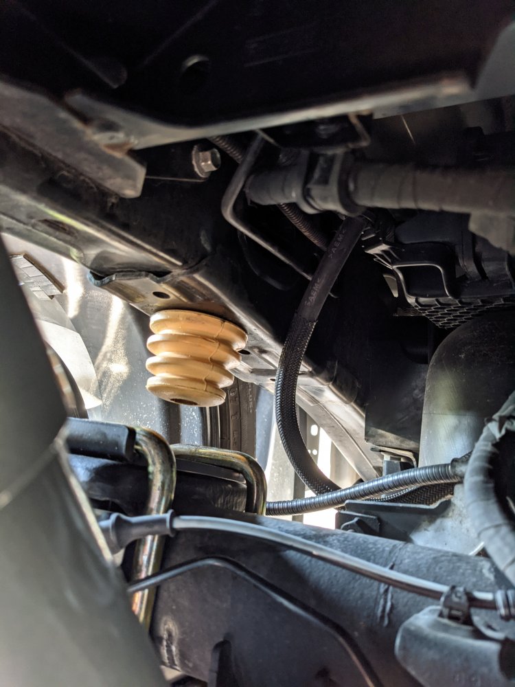
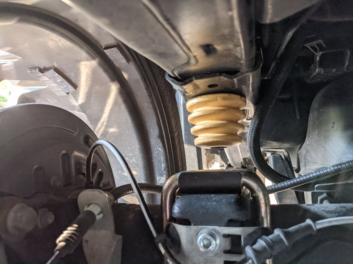
b) Install the supplied BELLTECH Bump stop 4923-001 by using the OEM bolt. (PIC 19)
c) Torque the U-Bolts to 90 Ft* lbs.
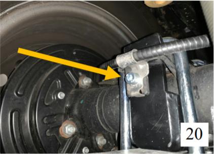
d) Connect the OEM brake line using the supplied M8 bolt & washer (BELLTECH #112001 & 110635 ) ( PIC 20)
6) CENTER CARRIER BEARING (CCB) MODIFCATION
NOTE: THIS MODIFCATION IS TO ADJUST THE DRIVELINE ANLGE TO PREVENT AS MANY DRIVELINE VIBRATIONS AS POSSIBLE. ( OUTCOME VARIES FROM VEHICLE TO VEHICLE)
a) Support the driveline with an adequate support stand.
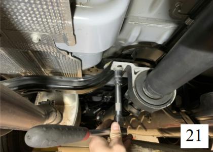
b) Remove the OEM bolts from the CCB using a 15mm socket. (PIC 21)
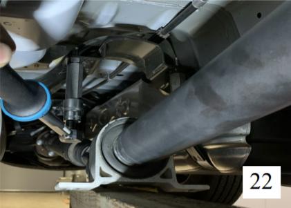
c) Install the BELLTECH CCB Adaptor Part # 6530-007 ( x2) in the original location of the CCB bolts. Apply blue thread-locker and torque to 16 ft-lbs. ( PIC 22)
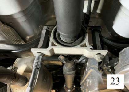
d) Flip the CCB and using the OEM bolts, attach the CCB back on to the BELLTECH CCB adaptor and torque to factory specifications. (PIC 23)
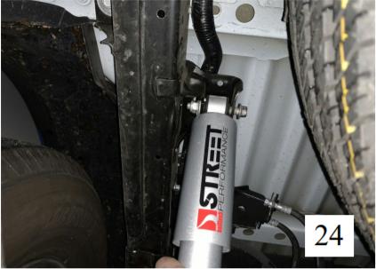
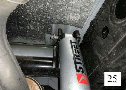
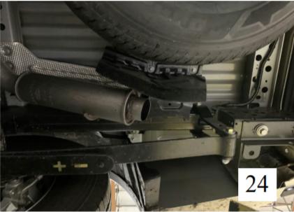
7) INSTALL THE REAR BELLTECH SHOCKS ( 2808EE) (PIC 24 & 25)
a) Use the provided bolt, BELLTECH # 112124 along with the OEM nuts for the bottom of the shocks
NOTE: Installing the OEM length shocks will not allow for correct travel.
!NOTE: FOR A 4 INCH DROP CONFIGURATION, A MODIFCATION TO THE EXHAUST IS NEEDED!
(FOLLOW THE NEXT STEPS)
8) EXHAUST MODIFCATION FOR THE 4IN SETUP
a) Locate the last turn of the exhaust. To make clearance for the leaf springs new position, we must cut the exhaust . See picture for reference.
b) Using a deburring tool, clean the edge of the exhaust so It does not have any sharp edges.
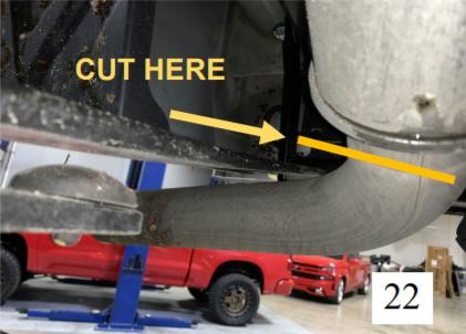
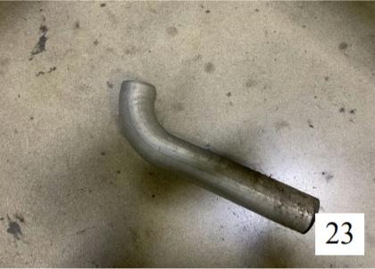
c) See PIC 23 & PIC 24 as a reference
9) FINALIZING THE INSTALLATION
a) Lower the axle until the weight of the rear of the truck is supported by the leaf springs.
b) Re-install wheels and torque to the Manufacturer’s specifications.
c) Check that all components and fasteners have been properly installed and torqued.
d) Lift the vehicle and remove the support stands. Carefully lower vehicle to the ground.
e) Check brake hoses, cables and other components for any possible interference.
f) Check for wheel/tire to chassis/body interference.
g) Once the vehicle is lowered safely on the ground.
TORQUE the shackle bolts in place to 90 ft-lbs.
h) Test-drive the vehicle in a remote location so that you can become accustomed to the revised driving characteristics and handling. Be aware that the vehicle will handle substantially different now that it has been lowered.
i) Take the vehicle to a qualified shop for a 4-wheel alignment.
j) Check all of the hardware and re-torque at intervals for the first 10, 100, and 1000 miles.
The FRONT of the vehicle MUST BE lowered accordingly for proper handling and performance and also to maintain warranty. We recommend using the BELLTECH 25021 lowering strut.
NOTE: the axle saddles ( 6530-020) have been designed to properly position the rear axle pinion shaft relative to the driveline so that vibrations are reduced/ eliminated. Do to manufacturing difference from truck to truck, these vibrations may be more prevalent. BELLTECH does NOT guarantee that all vibrations will be eliminated. If you experience vibrations take the vehicle to a driveline service shop immediately for driveline angle inspections and necessary adjustments. DO NOT drive vehicles exhibiting extreme driveline vibrations, as U-Joint wear could occur prematurely.
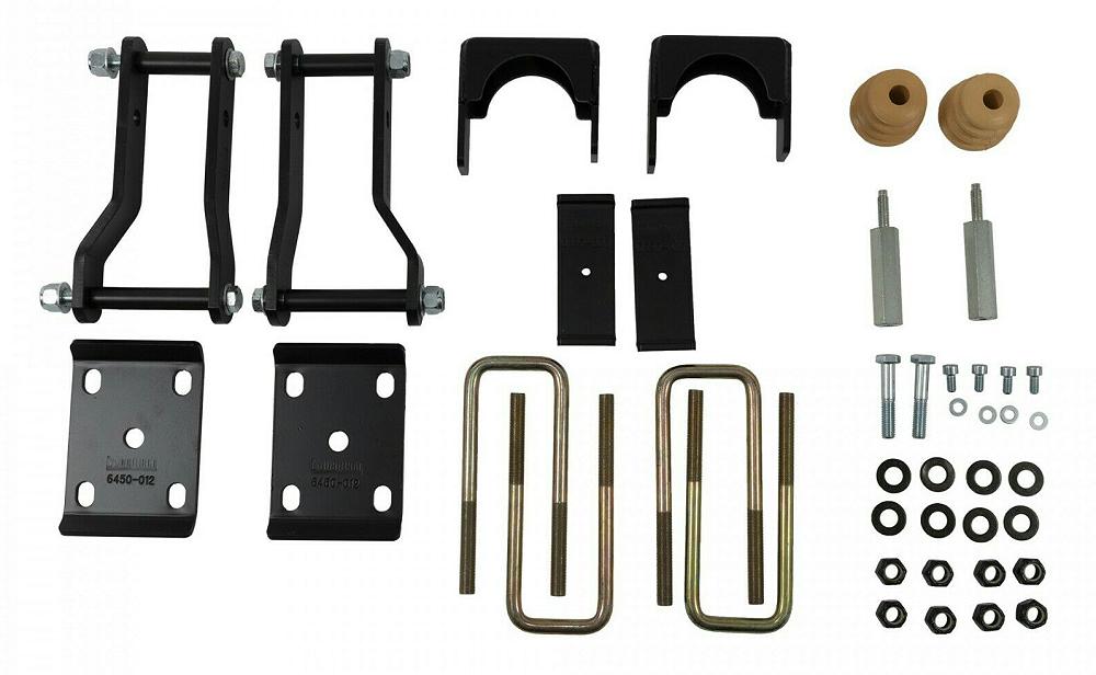
| 6530 Kit Parts List | ||
| Part # | Description | Quantity |
| 6530-020 | Axle Saddle | 2 |
| 6450-012 | U-Bolt Plate | 2 |
| 6530-003 | U-Bolt Spring Pad | 2 |
| 6530-007 | U-Bolt 9/16”-18 X 3.02” X 7.5” | 4 |
| 6530-045 | Center Carrier Bearing Adapter | 2 |
| 6530-015 | Rear Shackle (Outside) | 2 |
| 6530-017 | Rear Shackle (Inside) | 2 |
| 112401 | Spacer Tube (.57” x 2.7” 0.11”) | 2 |
| 112402 | Spacer Tube (.57” X 4.19” X 0.11”) | 2 |
| 112109 | 9/16”-18 x 4.5” | 2 |
| 112111 | 9/16”-18 x 6.0” | 2 |
| 4923-001 | Bump Stop | 2 |
| 110240 | Nylon Lock Nut 9/16”-18 | 12 |
| 110241 | Flat Washer A325 9/16”-18 | 12 |
| 112001 | M8 x 1.25 X 16mm (Brake Lines) | 4 |
| 110635 | 8MM Flat Washer (Brake Lines) | 4 |
| 112124 | M12 x 1.75 x 65mm (Lower Shock Bolt) | 2 |
| 6531 Kit Parts List | ||
| Part # | Description | Quantity |
| 6531-020 | Axle Saddle | 2 |
| 6450-012 | U-Bolt Plate | 2 |
| 6530-003 | U-Bolt Spring Pad | 2 |
| 6530-007 | U-Bolt 9/16”-18 X 3.02” X 7.5” | 4 |
| 6530-045 | Center Carrier Bearing Adapter | 2 |
| 6530-015 | Rear Shackle (Outside) | 2 |
| 6530-017 | Rear Shackle (Inside) | 2 |
| 112401 | Spacer Tube (.57” x 2.7” 0.11”) | 2 |
| 112402 | Spacer Tube (.57” X 4.19” X 0.11”) | 2 |
| 112109 | 9/16”-18 x 4.5” | 2 |
| 112111 | 9/16”-18 x 6.0” | 2 |
| 4923-001 | Bump Stop | 2 |
| 110240 | Nylon Lock Nut 9/16”-18 | 12 |
| 110241 | Flat Washer A325 9/16”-18 | 12 |
| 112001 | M8 x 1.25 X 16mm (Brake Lines) | 4 |
| 110635 | 8MM Flat Washer (Brake Lines) | 4 |
| 112124 | M12 x 1.75 x 65mm (Lower Shock Bolt) | 2 |