• Welcome Visitor! Please take a few seconds and Register for our forum. Even if you don't want to post, you can still 'Like' and react to posts.

Using factory ignition switch in a 302 w/Holley Terminator


Bee8Ranger

New Member
U.S. Military - Active
Joined
Jun 8, 2025
Messages
3
City
Las Vegas
Vehicle Year
1991
Transmission
Automatic
Hey all,

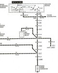
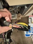
I'm in the middle/tail end of my 302/AOD swap into my 91 ranger (3.0/5sp originally) and I'm looking for some assistance in using the factory ignition switch for start/run. I've completely removed the factory harness and ECU in favor of a Holley terminator X, and I would like to avoid using a standalone push button ignition switch if possible. All of the wiring diagrams I've been browsing indicate that I can simply apply a dedicated 12v constant to the switch and then utilize the other appropriate wires/switch outputs to trigger crank. That's about the limit of my understanding of factory style ignition switches. My questions are...where do I apply power to the switch? From what I've seen, the common color for switch power across multiple diagrams is yellow, so would i apply power to one or both in the pic of my ignition wire harness? and once power is applied, i assume brown/pink is the trigger, and red/L Green is the 12v switched? Any help is appreciated!
 

Attachments

  • ignition switch.jpg
    ignition switch.jpg
    103.8 KB · Views: 30
  • Switch wiring.jpg
    Switch wiring.jpg
    186.2 KB · Views: 36
  • ranger.jpg
    ranger.jpg
    332.9 KB · Views: 34
Are you going to use the ignition switch for other duties like the accessories/blower fan/radio/etc? If you are, I would run two 10 gauge wires, one to each yellow wire, and then run these all the way back to the starter relay or the battery with two fusible links or two 60 amp mega fuses as close to the + connection as possible. This will give you max options for using the ignition switch.

The diagram below shows more clearly what each color does in each switch position.

The brown/pink is hot in start only. The red/lightgreen is hot in run only. You can see the factory tied these two together and ran them as a single wire to the ignition. You can see the pink went to the starter solenoid. Grey/yellow went to some higher power accessories.
1991 ignition switch.png
 
Are you going to use the ignition switch for other duties like the accessories/blower fan/radio/etc? If you are, I would run two 10 gauge wires, one to each yellow wire, and then run these all the way back to the starter relay or the battery with two fusible links or two 60 amp mega fuses as close to the + connection as possible. This will give you max options for using the ignition switch.

The diagram below shows more clearly what each color does in each switch position.

The brown/pink is hot in start only. The red/lightgreen is hot in run only. You can see the factory tied these two together and ran them as a single wire to the ignition. You can see the pink went to the starter solenoid. Grey/yellow went to some higher power accessories.

This is exactly the response i am looking for!
I will eventually want to wire in radio/blower/etc, but were about to move cross country so i'm just looking for the basics right now to get it started and movable onto a trailer. I will take your advice on both the yellow wires.

I'm looking to eliminate the starter solenoid and run it through a relay, so I'll be using the pink wire as the trigger, correct? Then i can use the brown and pink as the crank power for the ignition, and the red/light green as 12V switched power otherwise.

Sound about right?

Thank you again, and you just broke down what was the last wall in me getting the start/charge circuits completed!
 
Consider the brown/pink and the red/lightgreen as one ignition power wire that is hot during start and run since they are both tied together to one wire.

Then the pink will be the cranking wire.

The switch seems overly complex, but the beauty of it is having separate sections, one section doesn't interfere with the other. You can have the brown/pink wire feeding the ignition during cranking, and that circuit will not be mixed up in the pink wire circuit which is also hot during cranking, keeping those two starting power chores separate from each other.
 
Got it! Thank you so much. Hope this is useful for some in the future!
 

Sponsored Ad


Sponsored Ad

TRS Events

Member & Vendor Upgrades

For a small yearly donation, you can support this forum and receive a 'Supporting Member' banner, or become a 'Supporting Vendor' and promote your products here. Click the banner to find out how.

Recently Featured

Want to see your truck here? Share your photos and details in the forum.

Ranger Adventure Video

TRS Merchandise

Follow TRS On Instagram

TRS Sponsors


Sponsored Ad


Sponsored Ad


Amazon Deals

Sponsored Ad

Back
Top