• Welcome Visitor! Please take a few seconds and Register for our forum. Even if you don't want to post, you can still 'Like' and react to posts.

Tachometer Install on 1984 2.3L


RJMacReady

Well-Known Member
Joined
Oct 7, 2020
Messages
67
City
Seattle
Vehicle Year
1984
Engine
2.3 (4 Cylinder)
Transmission
Manual
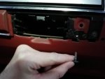
Hey folks, trying to install a tach. It's the 4 wire style (power, ground, light, engine signal).

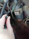
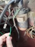
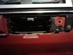
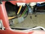
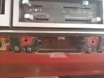
Found a good spot for the ground but none of the diagrams I've found look quite like what I'm seeing in my truck so I could use some help figuring out where to to put the rest. Here's a shot of my fusebox and my coil. Anyone know what I'm supposed to do here?
 

Attachments

  • IMG_20201201_155939.jpg
    IMG_20201201_155939.jpg
    36 KB · Views: 164
  • IMG_20201201_155917.jpg
    IMG_20201201_155917.jpg
    36.7 KB · Views: 167
  • IMG_20201201_155912.jpg
    IMG_20201201_155912.jpg
    44.4 KB · Views: 154
  • IMG_20201201_155811.jpg
    IMG_20201201_155811.jpg
    57.6 KB · Views: 150
Tach signal comes from Coil "-" so the green wire terminal in picture

You don't want Tach to be "on" when key is off, so you need a 12volt key on wire or fuse
There will be a Red/light green stripe wire that comes out of ignition switch(under steering column) that runs out to engine bay, it has 12v key on
That same Red/light green wire is at the Coil "+" terminal in your picture so you could use the lead you are holding for 12v key on

Ford uses a Light Blue/red stripe wire for dash lights, it comes out of the main light switch, and has dimmer control, you can tap that wire at the switch to get dim-able back light for tach
 
That's very helpful, thank you! Let me make sure I understand correctly. The cable with the plastic connector on it is key-on 12 volt, and the double green on the right side is the tach signal? Does it matter which of the two on the double green that I tap?
 
Yes, use a volt meter(or test light) to confirm 12v on that short wire with key on and no volts with key off, you could use a 5amp inline fuse on your added wire to the tach just because this is a main 12v wire and a short on your added wire thru firewall would be a BAD thing, i.e. melted wires and engine would stop running :)

And just FYI, that short wire and connector was used for a Radio Noise suppressor capacitor, as coils would cause static on AM stations when engine was running

They can look like this: https://www.fullsizebronco.com/attachments/f-18832-4_20180411220418-jpg.152172/
Or this: https://d3d71ba2asa5oz.cloudfront.net/12006198/images/inl12834_325__1.jpg


No, doesn't matter, you can tap either green/yellow stripe wire to get tach signal, but these wires do make the spark so make sure you don't break their connection to coil
 
Last edited:
Awesome, I'm going to put a fuse in then. Better safe than sorry.

These little plastic taps they gave me with the gauge are junk, I'm going to have to order some in a different style.

I really appreciate all the detail, I knew signing up for this forum was a good idea.
 
Got some T-Tap style connectors in 12 gauge, those did the trick. I tapped the two wires you mentioned and now I'm getting the right RPM readout! Pretty awesome.

I haven't tried to get up under the dash to find that dimmer switch wire, I'll give that a shot tomorrow.
 
Two screws will let you will drop the ashtray bracket, where you can pick up the Lt Blue / Red stripe wire for your tach light. It's easier getting it there than at the headlight switch.
 
Trying to get into that ashtray area, I dropped 2 screws from the top of it, but it wasn't coming off. Took some trim off the right and found a third screw.. Not sure if I'm on the right track.

I do see a set of wires back behind the cage though.

Appears to be hold on by a third almost rivet looking kind of thing? Not sure what I'm seeing.
 

Attachments

  • IMG_20201208_150505.jpg
    IMG_20201208_150505.jpg
    83.3 KB · Views: 152
Here's a better pic.
 

Attachments

  • IMG_20201208_150453.jpg
    IMG_20201208_150453.jpg
    104 KB · Views: 146
There's a similar screw on the left side; carefully pry the trim off to the left of the ashtray to expose it.
 
Got it all dropped without too much trouble. Tapped the light blue with the red stripe and it's just what I needed. Now I the gauge has light and dimmer function! Thanks everyone, feeling good to have pulled off my first project of this sort.

Really wanted a good view of it right next to the speedometer, so I stuck it on the steering column. I didn't have a hose clamp so I 3d printed one. May rework it so the size is better and I can close it with an M3 bolt or something.
 

Attachments

  • IMG_20201212_121341.jpg
    IMG_20201212_121341.jpg
    85.7 KB · Views: 141
  • IMG_20201212_121032.jpg
    IMG_20201212_121032.jpg
    55.6 KB · Views: 147
  • IMG_20201208_135137.jpg
    IMG_20201208_135137.jpg
    71.9 KB · Views: 144
Good job; I like how you mounted it!

Also kinda cool how both your red lines are at "55" : )
 
I would say 5,000rpm would be Redline for the 2.3l SOHC Lima engine
On 1983-1986 2.3l Max horse power is at 4,000rpm
Max torque is at 2,400rpm

So not many reasons to go above 5,000rpm
 
Last edited:

Sponsored Ad


Sponsored Ad

TRS Events

Member & Vendor Upgrades

For a small yearly donation, you can support this forum and receive a 'Supporting Member' banner, or become a 'Supporting Vendor' and promote your products here. Click the banner to find out how.

Recently Featured

Want to see your truck here? Share your photos and details in the forum.

Ranger Adventure Video

TRS Merchandise

Follow TRS On Instagram

TRS Sponsors


Sponsored Ad


Sponsored Ad


Amazon Deals

Sponsored Ad

Back
Top