Fuel pump(s) power
Battery(+)---(fusible link/fuse)-------Fuel pump relay-------------inertia switch------------Fuel pump(s)------ground
Fusible link will be attached to fender mounted Starter Relay(solenoid) post with Battery Positive cable
FP Relay(Green base) operation
Fuel pump relay's COIL gets 12volt when key is on, Red wire, this comes from EEC Relay(Brown base), EEC Relay also powers EEC(computer), Fuel injectors and spark.
Computer GROUNDS the COIL of the FP Relay to activate it which sends power to the inertia switch and then to the fuel pump(s)
Computer also Monitors voltage on the wire between FP Relay and inertia switch, this Monitor circuit will show 5 to 8 volts at inertia switch if key is on, FP Relay OFF, 0 amps so fuel pump is not getting power, just monitor voltage.
When you turn on the key, and each time you turn on the key, the computer will Boot Up and GROUND the FP Relay for 2 seconds, but only 2 seconds, you should see full 12volts at inertia switch at that time and then it will drop to the 5-8volt monitor voltage after 2 seconds.
Wiring colors for the FP Relay changed quite a bit, Red from EEC Relay was the only constant.
There is a test/bypass for the FP Relay's Computer Ground
On the main engine harness running to the computer will be the ViP/OBD1 connector
Diagram seen here:
http://www.therangerstation.com/tech_library/OBD_I.shtml
Fuel Pump Slot is IDed in drawing
If you put a Jumper wire from that slot to a Ground(battery -) then when you turn on the key the FP Relay will close and stay closed until key is turned off.
This doesn't hurt anything, you are just doing what the computer does
If you want to ID wires pull out the FP Relay from its Green Base
Key OFF
Test each slot in the base for 12volts, there should be only 1 slot that has 12volts, thats from the Fusible link(fuse) that comes from Battery, it has 12v all the time
Key ON
There should now be another slot with 12v, the Red wire slot, thats from EEC Relay
If you have the Ground Jumper in place on the ViP connector use meter to test for GROUND, slot with ground goes to computer
The wire color at the ViP connector for this Ground should be same color at the FP Relay base, "usually", but not always
That only leaves inertia switch wire, so you now have the 4 wires IDed
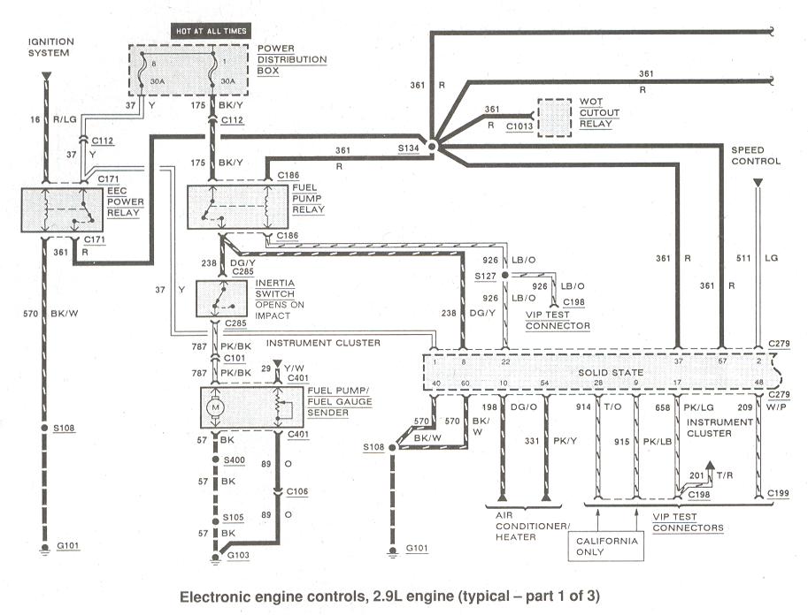
2.9l electrical diagram here:
http://www.therangerstation.com/tec...es/Diagrams_ElectronciEngControls2_9_1of3.JPG
It shows wire colors but..............grain of salt, Ford changed the colors often


