• Welcome Visitor! Please take a few seconds and Register for our forum. Even if you don't want to post, you can still 'Like' and react to posts.

Electrical Problems


RonneyJAyala

Well-Known Member
Joined
Feb 20, 2015
Messages
131
City
Eugene OR
Vehicle Year
1992
Transmission
Manual
I have a 92 Ford Ranger, v6 4.0 liter, and before hand it was my grandmas. But, I'm having a bunch of issues with the battery not staying charged, or not getting a charge, I put a new altenator in to see if that's the problem, but it's still not working right, the battery isn't getting any charge. Any possible help would be greatly appreciated!
 
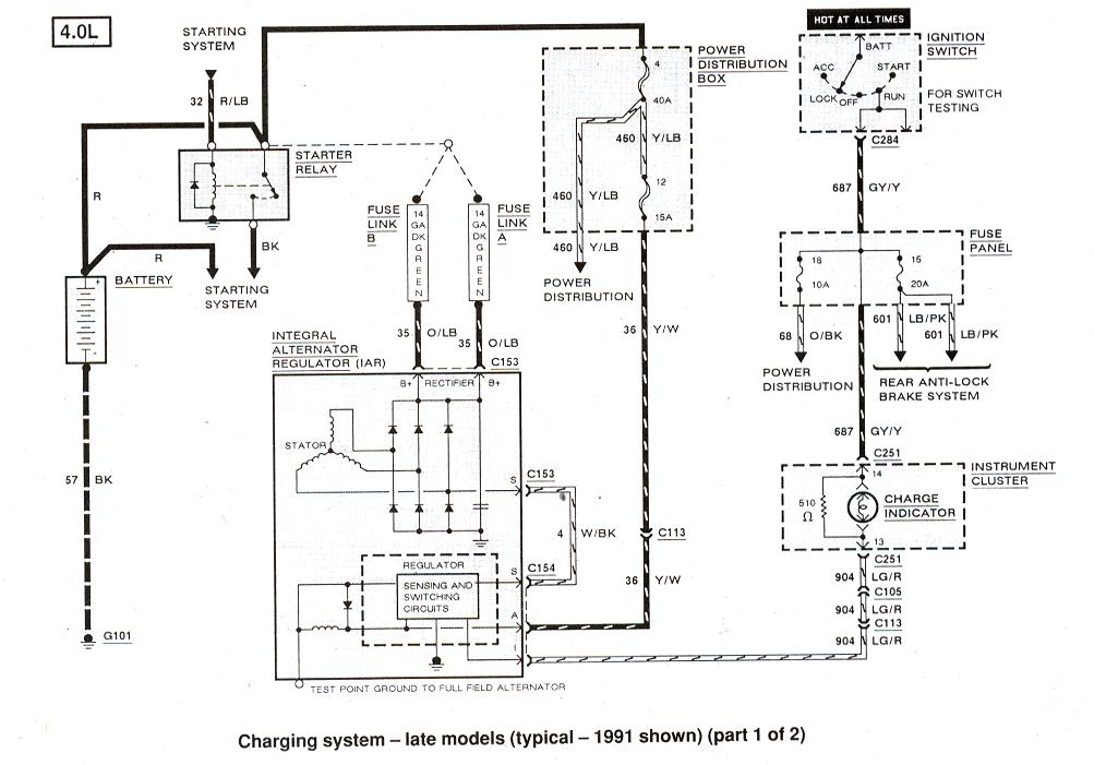
You will need a Volt Meter to test charging system.
Set Meter for 20vDC or DC Volts

First test voltage at battery, should be 12.3v to 12.8volts, Key should be OFF

On the back of the alternator is the B+ terminal, larger wire or wires attach there.
Leave meter's Black probe on Battery -, the Ground terminal, and put Red probe on B+ alternator terminal, you should read the same voltage, 12.3v to 12.8v(battery voltage).
If not then Fuse or Fusible Link(s) is blown.
'92 4.0l could have either, look in engine fuse box for 60Amp fuses, usually #3 and #7.
Fusible Link is a short wire that will act like a fuse and break if overloaded, find the Starter relay(where Battery's + cable goes), on the same post with the battery cable you will find the Fusible links, they will be Dark Green wires, make sure they are not broken.

If you have Battery Voltage at the B+ terminal on the alternator then remove the 3 wire connector on the alternator.
It will have a White wire with black stripe(W/BK), a Yellow wire with white strip(Y/W) and a Light Green wire with Red stripe(LG/R)
Test Y/W wire, Black probe still on battery -, Red probe on Y/W wire, you should see Battery Voltage there, if not check fuse in engine Fuse box, #4 40amp, and #12 15amp.

If Y/W wire has battery voltage then test LG/R wire next, this wire is the ON/OFF switch for the alternator.
When you turn on the key, this wire should have battery voltage, turn on key, black probe still on battery -, red probe on LG/R wire, you should see battery voltage.
If not then Voltage meter/battery light wiring in dash could be the problem.
When you turn on the key, the ignition switch sends voltage to Volt meter in dash, and/or Battery light in dash, then to the LG/R wire which turns on the alternator.

Wiring diagram here: http://www.therangerstation.com/tech_library/EDiagrams/files/Diagram_charging_1991_1.JPG
 
Last edited:
The battery is around 11.2 volts, and is from 2002. I forgot to mention those. So I can't start it anymore, without roll starting it, or jumping it. But another thing is, usually you can test an altenator by removing the positive wire off the battery, well when I do that, the motor instantly dies. Could it be because I had a motor swapped from a 93'? Or what?
 
Don't pull the wires off the battery while running, that can cause the alterator diodes to stop working. Your low battery voltage is what is the first thing to look at. Use a battery charger and charge the disconnected battery on low overnight. Take a reading, it should be in the range that RonD said. If the battery doesn't charge up properly then you need a new battery. A 12 year old battery is probably toast.
 
Yeah, I'm getting a new battery hopefully tomorrow. But I've always been told that you could test an alternator by removing the positive on the battery and if the motor continued running, it was fine, if not the alternator was bad. And if I do get a new battery, would the issue of charging still be there? Because at the moment the battery isn't being charged. I still need to go get another bench test on the alternator.
 
You may have blew the alternator when you pulled the wire. Do get it tested, most places test for free hoping you will buy from them.
 
I'll get it tested tomorrow, and if I did I have a warranty on it


Sent from my iPhone using Tapatalk
 
Just FYI for future reference, testing an alternator by removing either battery cable was from the VERY old days when using generators and alternators with External regulators.
You will damage electronics in newer systems when you do this.

You also shouldn't use jumper cables on newer vehicles while vehicle is running, shut off jumping vehicle remove battery cables then connect the good battery to the dead vehicles battery with jumper cables and try to start it.

Car Battery life is 5-7 years, even if unused, it's a chemical thing, but the low 11.2volts won't effect the tests outlined above to determine if vehicle wiring is OK, Battery Voltage at the wires should be 11.2v.

The tests have nothing to do with alternator or battery, they are just to see if wiring and fuses are good or are the problem.

If you want to test if alternator is working use volt meter, working alternator will show 13.5volts to 14.9volts with engine running at the battery.
Above 14volts just after starting engine, then it will slowing go down to 13.5v after a few minutes, so it recharges the battery after being drained by starter motor(14v+), and then so battery doesn't get "cooked", alternator/voltage regulator lowers the voltage to "maintenance" charge, approx. 1volt above battery Voltage.
 
Last edited:
Like how old? Because a friend of mine said you could run a vehicle off just the alternator, said he did it in his 97 Toyota Tacoma. But for the tests, I didn't get time around to do them, will do it today though when I get home, and will take pictures of each position


Sent from my iPhone using Tapatalk
 
??

Electrical system in a vehicle does run off alternator power while engine is running, but that has nothing to do with disconnecting battery while engine is running.
The battery is part of the reference voltage in the circuit.

In the "old days" external voltage regulators used relays, mechanical contacts that opened and closed to maintain a voltage range.
When voltage regulators were moved inside the alternators they used transistors to maintain voltage range.
Transistors don't handle voltage surges too well, nor should they need to, when you remove the battery voltage from the circuit you create a voltage surge or drop, and then a surge or drop when you reconnect it, mechanical relays could handle this transistors not so much, lol.
There is also the other electronics in the vehicle now-a-days to consider, they all have transistors and "chips" that don't handle power surges well either.

$20 volt meter to test alternator or replace alternator for $100 by removing battery cable, seems like an easy choice :)
 
Well today I'm getting a new battery due to it being so old, and getting another bench test for my alternator, which if broken had a warranty.


Sent from my iPhone using Tapatalk
 
Checked all the wires you told me to check RonD, they all came up okay, so I'm figuring it's just the alternator and battery combo that's all messed up. Bench test came up bad on the alternator, so I'm gonna wait for the battery to ce in and a new al


Sent from my iPhone using Tapatalk
 
969e9b1f73199fa00a897625a175ce46.jpg


So, reviewing all the connections and such I stumbled upon this diagram, because again still not charging when I know the alternator and battery are working. But what I noticed is I don't have the little 15amp fuse for the alternator!! Anyone know what that fuse does? And if It would solve my no charging problem?


Sent from my iPhone using Tapatalk
 
Last edited:
Your '92 was a transition year for wiring changes.
Ford was switching from Fusible links to Fuses for alternator circuit.
A Fusible Link is a short colored wire that will separate, without causing a fire, if it's amp rating is exceeded, so similar to a fuse, but these were used before "slow blow" fuses were common, they can absorb amp spikes, heat up, without blowing every time.

Here are the two wiring diagrams during this change:
1991 and earlier: http://www.therangerstation.com/tech_library/EDiagrams/files/Diagram_charging_1991_1.JPG
You will see the 2 fusible links used to connect alternator output to Battery(starter relay)
And you will see the 40amp #4 and 15amp #12 fuse used to connect voltage regulator(in alternator) to battery

After 1991, maybe: http://www.therangerstation.com/tech_library/EDiagrams/files/Diagram_charging_1991_2.JPG
In this wiring model the fusible links are gone and just fuses are used, two 60amp slow blow fuses.

Alternator wiring is the same on both just the method of fusing the circuit is different.

In your diagram of the Power Box you have two 60amp alternator fuses(#3 and #7), so the 15amp #12 fuse wouldn't be used
On the alternator wiring the Yellow/white wire may just be run over to the B+ terminal instead of the Power Box, I have seen it both ways.

I guess the question is which wiring system was used on your '92?
 
Last edited:
Mine looks a lot like the second one, I don't have any fusible links, just straight fuses. Without the 15amp #12 one


Sent from my iPhone using Tapatalk
 

Sponsored Ad


Sponsored Ad

TRS Events

Member & Vendor Upgrades

For a small yearly donation, you can support this forum and receive a 'Supporting Member' banner, or become a 'Supporting Vendor' and promote your products here. Click the banner to find out how.

Latest posts

Recently Featured

Want to see your truck here? Share your photos and details in the forum.

Ranger Adventure Video

TRS Merchandise

Follow TRS On Instagram

TRS Sponsors


Sponsored Ad


Sponsored Ad


Amazon Deals

Sponsored Ad

Back
Top