• Welcome Visitor! Please take a few seconds and Register for our forum. Even if you don't want to post, you can still 'Like' and react to posts.

86 Ranger AC wiring colors and connections


BGS

Member
Joined
Jan 19, 2014
Messages
12
City
Merida Mexico
Vehicle Year
1986
Transmission
Manual
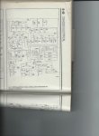
The previous owner converted this (2.9) truck to AC. He used a toggle switch to control the AC instead of installing the correct dash control head. He seems to have also added a wire (yellow) to the Relay. I've looked up many schenatics on the net and can't seem to find one where the colors match what I have. All seem consistent with the dash control having Green/Purple and Brown orange.
The relay has: Blue/red which is connected to the Vacume control. Two yellows jumped between two poles and another yellow lead that was used with a toggle swictch the previous owner installed instead of the "Dash control".
The vacume control has two leads. The blck goes to the compressor and the Black/red comes from the solenoid.
Does anyone have a schematic showing these colors? Or can someone assist in sorting out how things are powered/connected after the dash switch.
 
Yellow wire is usually the Power wire from the 10A fuse in the fuse panel.

Since it was an add-on he may have pulled the harness from another Ford model which is why the colors don't match.

If you have an '86 Ranger A/C wiring diagram then I would re-label it to match your colors, this may help you make sense of current wiring

Thanx Ron: I hadn't thought that a different harness might have been used. My fuse panel and manual only shows a 30 amp fuse for the blower & AC. Where is the 10 amp wire to the relay supposed to be connected? He had it trapped in the 30 ampfuse position with an inline fuse and I have disconnected all of it in anticipation of wiring it correctly.
 
It looks like they used the "factory installed" heater box set up etc. and then used their version of the dealer installed set up. The lt grn/purple wire is actually there on the pass side fender well. Mounted on the heater box is a relay they installed to operate the clutch magnet on the compressor with the red terminal spliced into the Blue/red of the fan control resistor terminals (?). So I am surmisising that when the dash control for the factory is installed the A/c mode will energize the lt grn/purple which goes directly (according to the diagram) to the A/C pressure switch, and then out to a blck/yel going to the EEC, A/C clutch Coil and Vacume valve solenoid. It is the distribution (Harness?) of these yel/blcks that I now need information on. I can't seem to find the harness connections for them.
Does anyone have pics of the A/C pressure switch & Vacume valve solenoid? It would help.
 
2.9 AC Wiring

Looks like you're on the right track. I have a Haynes manual that shows a red wire to the relay coil with LtGrn/ppl from the AC control to the clutch cycling pressure switch. Tan/yellow from the pressure switch to the cut out relay with a Blk/yellow to the AC clutch.
 

Attachments

  • AC Relay Wiring Dia (745x1024).jpg
    AC Relay Wiring Dia (745x1024).jpg
    58.6 KB · Views: 116
Looks like you're on the right track. I have a Haynes manual that shows a red wire to the relay coil with LtGrn/ppl from the AC control to the clutch cycling pressure switch. Tan/yellow from the pressure switch to the cut out relay with a Blk/yellow to the AC clutch.

Thanx: Unfortunately your pic is too small to read. From your description it does sound like a "dealer Installed" set-up.

I received what was supposed to be a "factory" control head from the states, however instead of a Two conductor AC switch it came with one with 3 leads (???!!!) my gawd I wish folks would do stuff properly the first time. I am going to try to get the correct AC switch and connect pin 86 on the relay to the green/purple that is on the fender well. # 87 to the compressor clutch, 86 to ground and 30 to an "ignition on" source. Hopefully I can get the switch and this works.
Does this sound reasonable?
 

Sponsored Ad


Sponsored Ad

TRS Events

Member & Vendor Upgrades

For a small yearly donation, you can support this forum and receive a 'Supporting Member' banner, or become a 'Supporting Vendor' and promote your products here. Click the banner to find out how.

Recently Featured

Want to see your truck here? Share your photos and details in the forum.

Ranger Adventure Video

TRS Merchandise

Follow TRS On Instagram

TRS Sponsors


Sponsored Ad


Sponsored Ad


Amazon Deals

Sponsored Ad

Back
Top