Curious Hound
I know a guy with a website
TRS Forum Moderator
TRS Event Staff
⭐Supporting Member
💻 TRS Socials
Article Contributor
TRS Event Participant
TRS 20th Anniversary
TRS 25th Anniversary
VAGABOND
U.S. Military - Veteran
GMRS Radio License
- Joined
- Feb 7, 2016
- Messages
- 20,230
- Points
- 1,601
- Age
- 61
- City
- Wellford, SC
- State - Country
- SC - USA
- Other
- 2002 F250, 2022 KLR 650
- Vehicle Year
- 1993
- Vehicle
- Ford Ranger
- Drive
- 4WD
- Engine
- 3.0 V6
- Transmission
- Manual
- Total Lift
- 6"
- Tire Size
- 35"
- My credo
- In theory, theory and practice are the same. In practice, they are different.
Difficulty: Medium - high
Time to Install: 4-10 hours depending on Rust level and tools available
Disclaimer: The Ranger Station.com, The Ranger Station.com Staff, nor the original poster are responsible for you doing this modification to your vehicle. By doing this modification and following this how-to, YOU, the installer, take full responsibility if anything is damaged or messed up. If you have questions, feel free to PM the original poster or ask in the appropriate section of The Ranger Station.com forums. ALSO, at the time of this writing, neither TheRangerStation.com or the author are sponsored by any specific companies or brands that my be mentioned herein.
Tools:
Video;
Cab Mount Puller Tool;

Time to Install: 4-10 hours depending on Rust level and tools available
Disclaimer: The Ranger Station.com, The Ranger Station.com Staff, nor the original poster are responsible for you doing this modification to your vehicle. By doing this modification and following this how-to, YOU, the installer, take full responsibility if anything is damaged or messed up. If you have questions, feel free to PM the original poster or ask in the appropriate section of The Ranger Station.com forums. ALSO, at the time of this writing, neither TheRangerStation.com or the author are sponsored by any specific companies or brands that my be mentioned herein.
Tools:
- #2 philips Screwdriver
- (2 minumum) 1/2" ratchet/Breaker Bar with extensions
- 15mm socket (1/2" drive)
- 18mm socket (1/2" drive)
- 21mm socket (1/2" drive)
- 24" pipe wrench
- Jack and cribbing as needed to lift the cab
- Wheel Chocks
- Something to pry rubber grommets and body clips
- Optional "Body Mount Puller Tool" - design included at end of article
- miscellaneous shop supplies
- A good friend (optional, but handy. Buy his/her lunch afterward)
- New cab mount Bushings for your truck model/year
- Might need new bolts
- (2) 1/2" flat washers
- Penetrating oil
This job is not complicated. It does take some upper body and arm strength to wrestle tight and possibly rusted fasteners apart. Time to complete will vary depending on the actual conditions and rust levels on your truck. Later in this article, I will outline a tool you can make that greatly eases the process of removing the old middle and rear bushings. Link to video at the end of this procedure. This article was developed on a 3rd generation Ranger (’93-’97). I am assuming other older generations, up to 2011 are the same or similar. At least it will give you some insight on how Ford designed these mounts. Adapt as necessary for your truck.
Procedure:- Park the truck on flat, level ground, preferably pavement. Set parking brake. Chock wheels so it can't roll.
- Spray the bolts with penetrating oil so it can start soaking in. How much does it help? Nobody knows. But it won’t hurt anything and you will want every advantage you can find.
- Remove the trim piece along the threshold at the bottom of the door opening. (4) philips head screws
- Remove the kick panel coming up the side wall. - Plastic push-pin
- Carefully pull back the carpeting to expose the rubber plugs over the mounting bolt holes – 4 locations
- For the middle and rear mounts, use the 18mm socket on the bolt head in the cab and the 21mm socket on the nut at the bottom. Loosen and remove the bolts. The nut on the bottom is attached to a washer and a sleeve that is pressed into another sleeve at the top of the bushing assembly. So, it will not fall out easily. See cutaway drawing of the assembly.
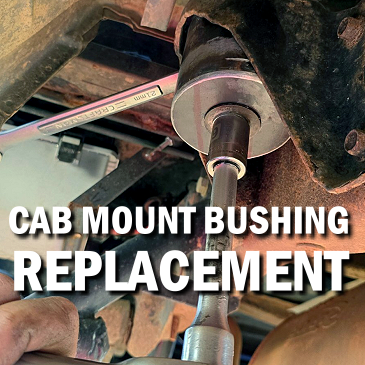
- Separate the lower and upper portions of the bushing and sleeve assembly from each other. This is a challenge. You may be able to pry them apart with pry bars. I found that to be very difficult and time consuming. I also tried beating them apart with hammer and punch with no success. So, I made a special puller to separate these pieces. Drawing and photos are in the “Special Puller” section at the end of this article. , TAKE NOTE OF WHICH PIECES GO IN EACH LOCATION. They are all different and fit in different locations – front / middle / rear.
- After removing the middle and rear assemblies on both sides, move to the front mounts. These are assembled differently and introduce their own special brand of fun.
- Using a 15mm socket to hold the bolt head at the bottom and using the 21mm socket, remove the nut at the top. You will notice that the bolt does not drop out of the hole.
- Find the structural rib next to the middle mount and lift one side of the cab until you have at least ½” of clearance between the cab and the top of the mounting bushings at the front. Just lift one side at a time.
- Now, comes the "fun" part. I recommend having a friendly helper. It is well worth the price of buying his lunch. Again, there is an upper sleeve and a lower sleeve. This time, the upper sleeve has internal threads. The bolt is threaded into the upper sleeve.
- Use the pipe wrench to hold the flat washer attached to the upper sleeve. Then use the 15mm socket to remove the bolt. Sounds easy on paper. Doesn’t it?
- Once all the fasteners have been removed, lift one side of the body until you have enough clearance to remove the old bushing assemblies. IMPORTANT NOTE; Before lifting, look for any cables, hoses, tubes, etc. that are attached to both body and frame. Loosen mounting brackets, cut zip ties, etc. as needed to make sure you do not pull something too tight when lifting the body. Remember what you disconnected so you can re-fasten as needed at the end. Also, again, TAKE NOTE OF WHICH PIECES GO IN EACH LOCATION. They are all different.
- Separate the metal sleeves/nuts/washers from the rubber pieces. Clean the rust from them so they can be re-used, unless you have replacements.
- To make things easier in the future, I drilled the threads out of the front upper sleeves. I will re-assemble with the bolt entering from the top, just like the middle and rear assemblies. The lower sleeves for the middle and rear seemed to have a bulge that made them fit tightly in their upper sleeves. I sanded that bulge away so the sleeves slid together easily.
- Match your new bushing pieces and the washer/nut/sleeve pieces to their proper locations. I greased the bushings and metal pieces to hopefully prevent corrosion and squeaks between the layers. If you do this, use a grease that will not attack and degrade the new rubber or poly bushings. I used “Superlube” (not a sponsor in any way). Keep the threads of the nuts and bolts clean and grease-free.
- Place the upper bushing pieces and their sleeves in their proper locations. In the video linked below, you will note that I am also raising my cab 1” by inserting hockey pucks with ½” holes drilled in their centers. This is the time to install those also. If installing a “lift” like this, longer bolts will be required.
- Insert the bolts from the top, making sure all original washers are in place. It is easier to do this before you lower the cab onto the bushings because the bushings are currently free to move so you can get them aligned. I also took the liberty of installing my front bolts from the top, instead of the way Ford had them. This required adding a flat washer (12mm or ½”) so the bolt head cannot pull through the slotted washer on top of the body sheet metal.
- Now, carefully lower the body onto the bushings.
- Assemble the lower bushing pieces, sleeves and nuts. DO NOT TIGHTEN YET. Leave them very loose so there is no binding when you lift the other side.
- Repeat steps 16 – 20 for the other side of the truck.
- Measure from the face of the frame to a known point on the body in 4 places (front driver side, rear driver side, front passenger side and rear passenger side) and ensure the body is centered on the frame. Push and shove it around until it is centered and straight.
- Tighten the bolts and nuts. I did not search for a torque specification. There might be one out there. 60ft-lbs seemed about right to me. Torque all the bolts to the same spec. NOTE; I found that the cab will bend slightly with different torque on various bushing assemblies. So, after getting them tight, make sure your doors open and shut nicely and have an even gap where they meet the body. ( assuming everything fit properly before you started) You can adjust the torque on the bolts to “bend” the cab slightly and change how the doors fit. I would not go much over 60 – 70 ft-lbs. But loosening some may also be helpful. Also, I used a small amount of blue thread-locker on the bolt threads.
- Inspect the truck to make sure you haven’t pulled anything too tight or pinched anything. Re-fasten anything you took loose in the beginning.
- Re-install grommets, carpet and trim pieces.
- Remove wheel chocks and clean up your mess.
Video;
Cab Mount Puller Tool;
Here is a simple sketch of the puller tool I made and showed up above. This is very useful for the middle and rear mounts. You have some leeway on what pipe to make it from. The key details are that the Inside Diameter must be large enough to fit over the bushings and metal washers. The Outside Diameter must be small enough to fit inside the cab mount brackets. The top plate must be large enough that it cannot slip inside the pipe. The plate doesn't even need to be round and you don't have to weld it together. It will just be more cumbersome to use if it is not welded.