
Introduction
Many Ford Ranger owners have installed a dual transfer case, or transfer case doubler, into their 1983-2011 Ford Rangers. Some have done so by making their own adapter plate and sector shaft. This time around, we’ll show you how some members have used a BW1350-BW1354 transfer case doubler kit by D&D Machine.
- D&D Machine
- (360)779-2500
- Pirate 4X4 User Profile: http://www.pirate4x4.com/forum/members/d.d.machine.html
Table of Contents:
- Clocking The Transfer Case
- Transmission Crossmember
- Doubler Support Bracket
- Linkage
- Extending The Shifter Fork
- Speedometer Cable
- Driveshafts
- Wisdon To Share
From Forum Member Kage:
This is my first foray into any transfer case. Thankfully it turns out that they’re quite a bit simpler than I thought they would be. I don’t know if the gear driven cases are any more complicated, but my guess is that they’re even simpler.
I’m using the D&D Machine kit from Duffy (he also makes the “Box For Rocks” kits for the Jeep stuff as well). The kit really is quite simple to put together (heck, even a goofball like me managed to get it done without too much of an issue). If you really had to hammer through it, you could probably knock this project out in a day easy (day + plus whatever time you need for the form-a-gasket to cure).
Duffy’s kit comes with the adapter plates, block off plates, all the bolts needed, shorter shift rail, and the all important splined shaft.

(D&D Machine Doubler Kit – Photo by Kage)
Once you have the kit, you’ll need a BW1354 (either an electric shift or manual shift will work as this is the rear case):
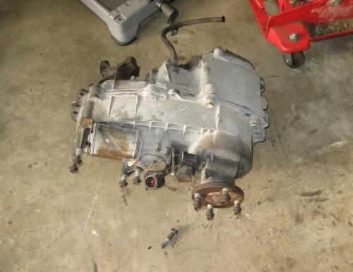
(BW1354 – Photo by Kage)
And also a BW1350 (Manual) case for the front:

(BW1350 – Photo by Kage)
Rear case portion of this is stupid simple to put together (BW1354 case). But before you can slap it together, you’ll need to do something about the breather as it will be in the way of the doubler adapter plate. Either drill and tap a new one, or make a 90° elbow work as I did.

(Transfer case breather – Photo by Kage)
Remove the stock breather and do a little clearance grinding on the case. Then grind your 90° elbow to allow it to spin onto the case, and stick your old breather vent into the 90° elbow to finish this part off.
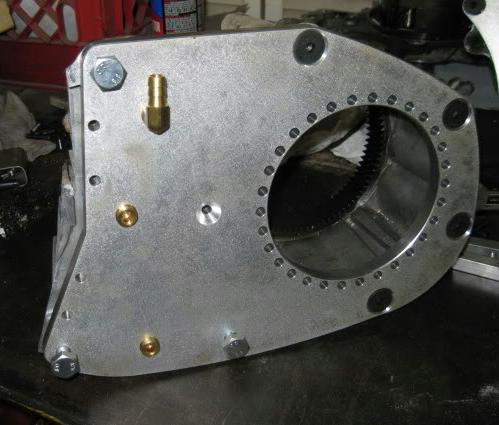
Once that’s done, you get to move to the first portion of your doubler build. That being, slapping on the rear adapter plate. Don’t forget to seal it up!

(Adapter plate installed – Photo by Kage)
(Adapter plate with sealant on the BW1350 and ready for the BW1354 – Photo by Bray D)
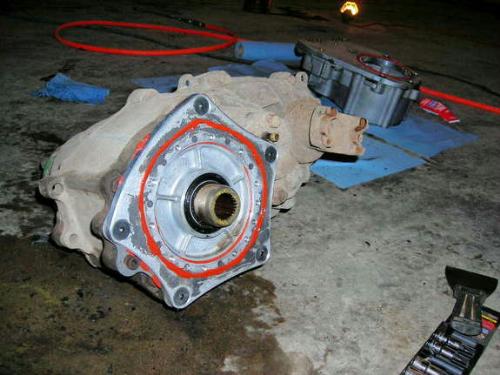
Now its time to start tearing the BW1350 apart to prep it for cutting. I started out with the transfer case and transmission adapter:

(BW1350 transfer case with transmission adapter – Photo by Kage)
Remove the transmission adapter:
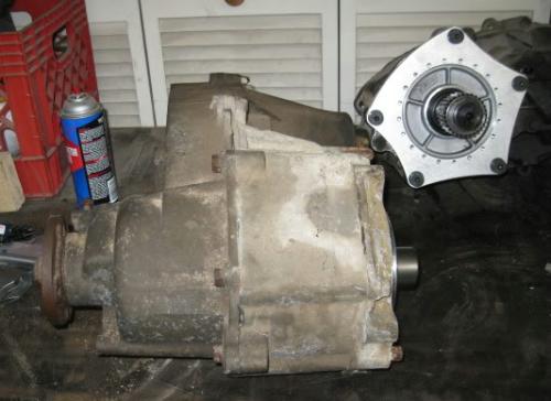
(BW1350 transfer case with transmission adapter removed – Photo by Kage)
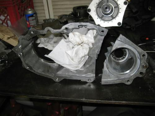
Unbolt the case halves and everything just falls apart (Note: if you pull the Rear yoke off, it is a little easier to split the case. I got lazy and just did it this way):

(BW1350 transfer case split open – Photo by Kage)
Once the case is split, lay the adapter plate on top of the BW1350 and mark a cut line. Make sure you leave some excess that you can clean up with a grinder later:

(D&D Machine doubler adapter plate installed to mark where to cut – Photo by Kage)

(BW1350 transfer case marked for cutting – Photo by Kage)
Remove the snap ring holding the front yoke on, and pull the planetary gear set out (bolts on the front of the BW1350), and get cutting!:
(BW1350 transfer case cut – Photo by Kage)
Slap the adapter plate back on to check your cut line and grind to your liking (Note: the vent shown was not supplied in Duffy’s kit, I picked that one up at Home Depot, more on that later):
(BW1350 case with adapter plate attached after cutting – Photo by Kage)
After you’ve done some grinding to get rid of the excess T-case stock, you get to start trimming the block off plates to fit. This is the one spot I’m a little disappointed in the kit. It would have been nice to have the plates a little closer to the right size (minor complaint, I realize that). After whacking off about 3/8” off the plates, and doing some rough grinding:
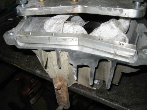
(Block off plates – Photos by Kage)
You can either have these welded on or just use some form-a-gasket to seal them off. I opted for the latter as this is just an Aluminum transfer case, I want to be able to pop these blocks off in the future if something were to happen the doubler case.
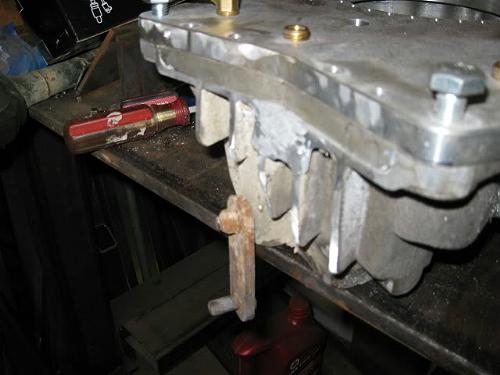
Once the blocks fit to your liking, its time to clean out the case and swap the shift rails out:
Seal up the adapter and block off plates, don’t forget to tighten up the screw for the new shift rail!:

(Sealing the block off plates – Photo by Kage)
After the sealant has set on the front case, slap some sealant on the surface between the adapter plates and screw them together. This is my only other complaint about this kit. Instead of having the shift rail screwed to the back side of the adapter plate (another place to possibly leak). It would have been nice to have the rail ‘float’ instead which would allow you to pull the shift fork out while tightening down these screws.
Getting under the shift fork is a pain for folks with big hands!
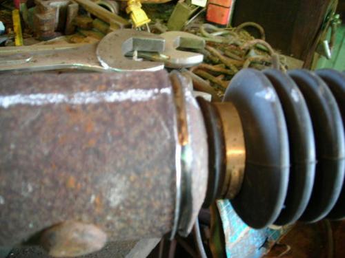
TIP: Drill a hole in the shift fork to allow you to get to the Allen bolt underneath it (I forgot to do that, it would have made life easy). This is also the point in which you get to clock the rear case.

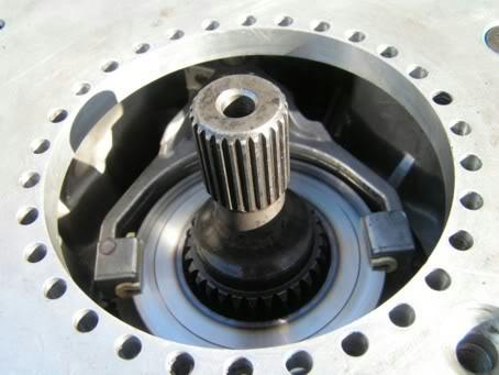
(Shift fork – Photo by Kage)
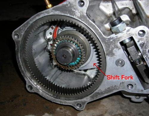
(View of installed shift fork – Photo by Bray D – Label by Jim Oaks)
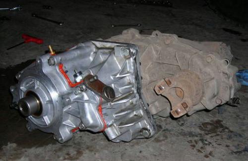
Plop the shaft in and slide the planetary set back into the front of the case (It helps to rotate it as you insert it). Don’t force it! It will slide in easily once everything lines up. Give everything a spin to makes sure it feels good while you’re at it. (And yes, you’re allowed to giggle as you make it spin in double low while its on the bench).


(BW1354 with BW1350 case attached after being cut – Photo by Bray D)
Now you just need to address the vent tube for the front case. In the latest revision of this kit, Duffy put a tapped hole on the adapter plate to be used for a vent. Since that hole sits higher than the stock vent, it’s wise to just plug up the stock vent tube hole:

(Stock vent – Photo by Kage)
(Vent plugged – Photo by Kage)
For the Main vents, I made them “T” into each other to less the amount of lines running around under my truck. At this point I think I’m going to run the vent line out back behind the cab, but that’s subject to change once I get the doubler under the truck.:

(T-fitting – Photo by Kage)
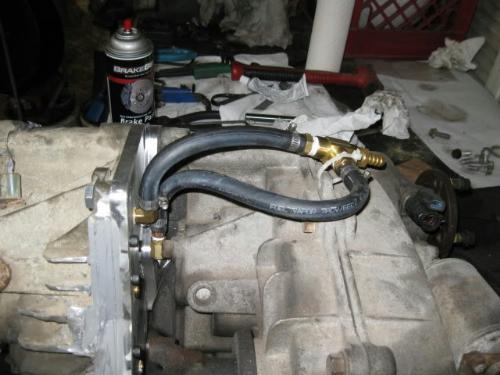
(Vent hose – Photo by Kage)
(Photo by Bray D)
Fill it up with fluid (about 3/4 of a quart) and slap it in the truck (I don’t have it in my truck yet so no pics). It looks like I’m going to get lucky with the linkage as my case came with the 1350 linkage for the AL4D. So it should work with my M5OD tranny and make life simple. If not, I’ll make it work.
As a side note, when looking at the guts of the 1350 and the diagram of the 1354E. I’m thinking it might be possible to take the mechanical linkage out of a 1350 and make it work in the 1354E case to lose the electric shift motor. If I come across a couple of cheap cases in the future, I might have to give this a try.
As another side note, If you have a spare 1354 laying around, you can pull the Planetary, shift fork, and slide gear to upgrade form the 4 gear set to the 6 gear set (1993+ 1354’s). I didn’t have that luxury, so I’ll just rock the 4 gear set. If it breaks, I’ll worry about it then.
Edit: The doubler add 6.75″ to your driveline
Clocking The Transfer Case:
The following photos show the differences between the cases clocked together in a stock position and then clocked by (1) bolt hole.

(Clocked in stock position – Photo by Kage)

(Driveshaft hits when clocked in the stock position – Photo by Kage)

(Clocked by one bolt hole – Photo by Kage)
You’ll notice in the second photo above that the driveshaft rubs on the front transfer case when it’s assembled in the stock / clocked position.
Clearance Issues:
(Before – Photo by Kage)

(After – Photo by Kage)
I also knocked off the little nub on top of the rear transfer case (see arrow) to give me a little more wiggle room:
(Before – See arrow – Photo by Kage)
(After – Nub removed – Photo by Kage)
I then stuck the T-Case back into the truck. It looks like with a little more trimming, I’ll be able to shove the whole driveline up a little further. That’s awesome as it’ll give me a flat belly.

(Clearance after some trimming – Photo by Kage)

(Doubler hang down before the clock: – Photo by Kage)

(Doubler hang down after clock – Photo by Kage)
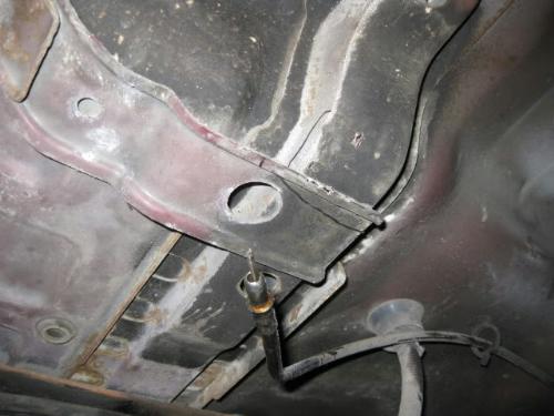
Transmission Crossmember:
When you add a doubler, the transmission crossmember needs to be modified so that the driveshaft doesn’t hit it. The photos below show how Bray D modified his crossmember:
(Transmission crossmember – Photo by Bray D)

(Transmission crossmember with bridge added – Photo by Bray D)

(Transmission crossmember cut out under the added bridge – Photo by Bray D)
(Transmission crossmember installed – Photo by Bray D)
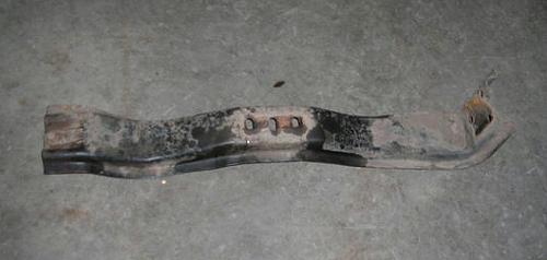
Kage made a whole new crossmember from 2″x3″x1/4″ wall stock.

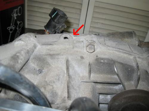
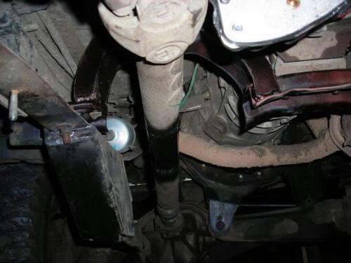
Doubler Support Bracket:
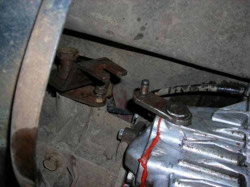
Since the transfer case hangs on the back of the doubler, some support it with an additional bracket. Bray D made the following bracket to mount to the frame, and the back of the transfer case.
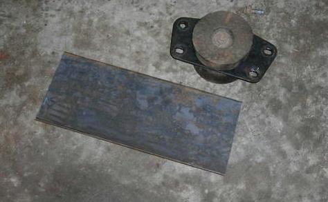
(Transfer case counterbalance and steel plate – Photo by Bray D)
The counterbalance is removed from the back of the transfer case so that a steel plate can be bolted on.
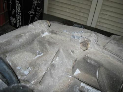
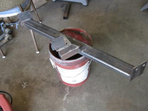
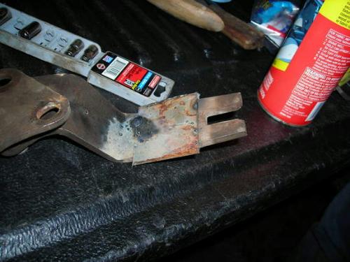
(Steel plate cut and mounted on transfer case in plate of the counterbalance – Photo by Bray D)
Then a tab is added to the top of the plate to make a support bracket.

(Crossmember and support bracket – Photo by Bray D)
An Energy Suspensions poly transmission mount bolts between the transfer case plate and a custom crossmember made out of tubing.

(New support bracket mounted in place – Photo by Bray D)
Shift Linkage:
When I bought the BW1350 to use for the doubler, it came with the linkage for the AL4D which is supposed to work with the M50D setup. I’m here to tell you it doesn’t, the upper portion of the linkage hits the back of the transmission in high range. So out came the welder and the chop saw!

(Stock linkage – Photo by Kage)

(Stock linkage cut – Photo by Kage)

(1/2-inch rod with threaded section welded on – Photo by Kage)
Get your knob of choice (I know it’s not original, but I like it) High range:

(High range – Photo by Kage)
(Low range – Photo by Kage)

(Photo of doubler linkage used by ‘4x4Junkie’ – Photo by 4x4Junkie)
(Shifter for the doubler right in front of the seat. It works by pushing down or pulling up – Photo by 4x4Junkie)
Extending The Shifter Fork:
When Bray D did his doubler build, his shifter wasn’t long enough and needed to be extended.

(Shifter – Photo by Bray D)
(Shifter length difference – Photo by Bray D)

(Cutting and extending the fork by 2-inches – Photo by Bray D)
(2-inch extension welded on – Photo by Bray D)

(Extension trimmed and cleaned up – Photo by Bray D)
Speedometer Cable:
The factory speedometer cable will be too short. You can use a longer speedometer cable from a Ford Aerostar van.
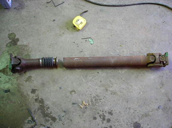
Driveshafts:
Adding the doubler will cause your rear driveshaft to be too long, and the front driveshaft to be too short. You’ll have to shorten one shaft and lengthen the other.
Shortening:
The cup (pilot) holding the splined shaft was removed by cutting the welds. Note that the shaft and cup were marked with a line to ensure it’s phased properly when you weld it back on. Do not not cut the cup off. It’s pressed in.
Make sure you cut through all of the weld. You can make pulling the splined cup out easier if you cut a slit down the tube. Since you’re shortening the shaft, you’ll be cutting off the section with the slit cut in it.
(Here the weld holding the cup (pilot) has been removed. This piece is pressed in. Do not cut it off here – Photo by Bray D)
Once it’s separated, the excess tube length was removed before being welded back together. A chopsaw works great for this.
4x4junkie recommends placing the driveshaft in a piece of angle clamped in a vise, with a piece of metal (as a reference point) almost just barely touching the splined end. As he rotated the shaft in the angle iron, any wobble became obvious where the spline was next to the metal. Once he had it straight, he tacked it, checked it again for straightness, and then welded it completely.
(Driveshaft photo by Bray D)
Lengthening:
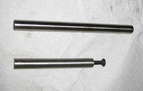
Step 1 – To lengthen the shaft, find the center and cut the driveshaft in half with a chop saw.

(Driveshaft photo by Kage)
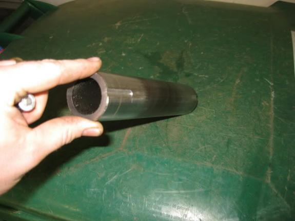
The Cherokee drive shafts are 1.75-inches on the ID, and they are made with 0.120-inch wall HREW tube. Since its HREW, you can’t just slap a slug in there and call it done.
Step 2 – Find some “Plug” material and mill (grind with a grinder) a couple of slots to clear the weld slag inside the tube. I’ve got an extra 1-inch that was driven into either side of the DS (I needed to extend the shaft 6.75-inches and my plug was 8.75-inches long, dig?). The extra bonus of the slots is that it makes it easier to keep the two ends of the drive shafts even:
(Driveshaft slug – Photo by Kage)
Step 3 – Hammer it all together as it’s a bit of a press fit. If you have some heat available to you, that’ll make life easier:

(Driveshaft welded up – Photo by Kage)
Step 4 – Step 4 is a little tricky. I don’t have a good way to hold everything in line, so I bolted the DS back in its home to check for the correct length. While it was there, I slapped a dial indicator on it to rotate and tap in line. This is far from ideal so I’m not so sure on how accurate my 0.020” run out reading really was. But as I said, worse case is I just have a spare shaft now. Add to it, I can’t really remember if this was a good shaft to start with so who knows how good it is at this point
Step 5 – Remove the now tacked together DS from the truck and burn everything home, clean off your slag and you’re done!
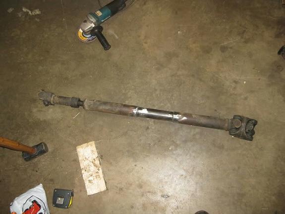
(Driveshaft finished – Photo by Kage)
Wisdon To Share From the discussion ‘Building a 1350/1354 doubler- any wisdom to share?‘:
Alignment:
Make sure the two cases are perfectly aligned with each other so the shaft doesn’t fatigue and break prematurely. Make sure it shifts correctly and holds in gear/position.
Planetary gear & Shift Fork (By slammer67):
Basically, my problem was the shifting setup on the BW1350. There was too much play in the shift fork/planetary, and the plastic shift guides would wear down fast causing the doubler to pop out of gear. It left me stranded twice. I started researching and found that you could use the planetary gear and shift fork setup out of the BW1354 in the BW1350.
I haven’t had any more problems since I switched to the BW1354 shift setup. You can use a BW1354 for the doubler, it’s the same setup, but finding a BW1354 manual might be frustrating. You can get a BW1350 manual and an electronic shift BW1354 to rob the planetary and shift setup. 1993 and later BW1354’s have 6-gear planetaries vs 4-gear for the earlier ones. I would suggest switching to the later shift setup. I think my problem came from a leak in the doubler. I didn’t watch it closely enough and the fluid got low and it overheated – which is probably where the excessive wear in my shift fork and planetary came from.
(BW1354 shift fork in BW1350 case – Photo by slammer67)
BW1354 Cases (By slammer67):
Later model (1994+) BW1354’s are a little stronger due to a six-gear planetary and a better shifting setup, but the early ones have the same 4-gear planetary as the BW1350’s
Leaks (By slammer67):
Be careful when you cut the case and weld on a block plate. I think that was one of my leakage problems. I left a small gap that the sealant didn’t fill too well. Some JB Weld and careful filing solved that. I don’t seem to have leaks now, and it’s been a good 6 months since I’ve messed with it.
Breather (By Bray D):
I relocated the breather hose to the top of the case and used the old breather location as a filler hole. This raises the fluid level in the case by a substantial amount. Problem is, it burps fluid out the top of the case, through the relocated breather hose. I’ve got the case out now (replacing slave cylinder in trans), and am having a guy weld a baffle inside the case to hopefully prevent the fluid from getting into the breather hose.
Helpful Discussion In Our Forum:
Kage’s Build Thread – The Lone Ranger – Kage’s ’94 X-Cab Leaf SAS and Bed Bob
Bray D’s Build Thread – Daily Doubler Build
Wisdom To Share – Building a 1350/1354 Doubler- Any Wisdom To Share?
Related Articles:
Transfer Case Doubler Overview & FAQ’s
1983-2011 Ford Ranger Transfer Cases
BW1354 Transfer Case Exploded Parts Diagram
Building a BW1350-1354 Transfer Case Doubler
Co-Authors
This article was put together by using real world experience from these forum members:
- Kage
- Bray D
- slammer67
Last Updated:
About The Author
Jim Oaks is the founder of TheRangerStation.com, the longest-running Ford Ranger resource online since 1999. With over 25 years of hands-on experience building and modifying Ford Rangers — including magazine-featured builds like Project Transformer — Jim has become one of the most trusted authorities in the Ford Ranger off-road and enthusiast space.
Since launching TheRangerStation.com, Jim has documented thousands of real-world Ranger builds, technical repairs, drivetrain swaps, suspension modifications, and off-road adventures contributed by owners worldwide. TheRangerStation.com has been referenced in print, video and online by enthusiasts, mechanics, and off-road builders looking for practical, and experience-based information.