• Welcome Visitor! Please take a few seconds and Register for our forum. Even if you don't want to post, you can still 'Like' and react to posts.

Did I wire this turn signal pigtail incorrectly?


I just use cheap meters, still, lol
Never worried about damaging them just don't care to spend money on tools that I only need general information from

It tells me what I need to know, I am not an electrician or electronics tester
For a vehicle its 12voltsDC or its not
In the house it 110voltsAC or its not

OHMs are a pretty wide margin, so exactly doesn't mean much, even specifically made resistors are +/- 5% or even 10%, so spot on accurate meter is fine, but for me ballpark tells me what I need to know

If you haven't bought a meter yet then my price point is $20, maybe $30 if it comes with extra tips like needles and/or clamps(alligator clips)
 
Ron, I ordered a multi-meter today off Amazon. I won't get it in time for this weekend. So I'll have to re-crimp the connector on the 25th weekend.
I'll update then or maybe before if I have any questions.
 
Huh....................I ordered this just last night with free shipping and it was already delivered. I guess I will do this repair this weekend.
 
I was experimenting with this new multi-meter today. And doing some reading also. I have a few more questions.

1. I tested the meter itself, where you touch the probes for continuity. I got a beep and reading of 000.3. When I test the meter itself it doesn't matter whether it is in manual or auto range........correct?

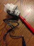
2. When I measure resistance to identify the ground wire on the new turn signal/parking map connector, I test it removed from the truck as shown in the photo below..............am I correct?
(you can see one probe touching bare wire one at a time, and another probe touching metal contact inside bulb socket)

When I clip off the incorrect wire crimp I did before, I don't have to necessarily disconnect the battery do I? I'll just have to connect it again anyway to touch wires for identfying turn signal and lamp wires.

P_20210918_130418_001.jpg
 
I was experimenting with this new multi-meter today. And doing some reading also. I have a few more questions.

1. I tested the meter itself, where you touch the probes for continuity. I got a beep and reading of 000.3. When I test the meter itself it doesn't matter whether it is in manual or auto range........correct?

2. When I measure resistance to identify the ground wire on the new turn signal/parking map connector, I test it removed from the truck as shown in the photo below..............am I correct?
(you can see one probe touching bare wire one at a time, and another probe touching metal contact inside bulb socket)

When I clip off the incorrect wire crimp I did before, I don't have to necessarily disconnect the battery do I? I'll just have to connect it again anyway to touch wires for identfying turn signal and lamp wires.

View attachment 65851

1. That is correct. Most of the time, you can just use the meter in "auto range" mode.

2. Yes. That is correct. Never test continuity/ resistance (ohms) of a live circuit. It can damage the meter or give you false readings.

3. As long as the circuit is de-energized, (light switch and turn signal switch OFF) that is fine. Otherwise, it is safer to disconnect the battery.

If voltage is present at the wires, it can be easy to accidentally touch live wire to ground or a negative wire. This causes a "short circuit" which can have extremely high currents, arcs, sparks and dangerous events.

A little extra learning; electricity follows Ohms law which states volts = amps(current) X Ohms(resistance). Manipulating that equation, Amps = Volts divided by Ohms. So, for example;

12 volts / 12 ohms = 1 amp
12 volts / 1 ohms = 12 amps
12 volts / 0.1ohm = 120 amps

A short circuit has 0 ohms resistance. So. That's would be Infinite current which burns wires and causes batteries to explode.
 
This is what I did about 30 minutes ago. Please read this carefully

1 I disconnected car battery

2. I tested old turn signal pigtail wires still wired in place in the engine bay

3. I set the meter on auto range/resistance/ohms

4. I cut off a small amount of insulation on all three pigtail wires. (not the truck wires these are crimped too)

5. touched one probe to bare wire and other probe to metal contact in pigtail socket with bulb removed and waited for reading

This is where is got a little confusing. In the bulb socket there are maybe 3 metal contacts. I would get different readings from these.

I just tried to find the most reliable one to touch the probe. This what I ended up with for the 3-wire connector

000.0 ohms
005.9 ohms
000.5 ohms

The goal here is to identify the ground wire on the pigtail connector

Did I do this correctly. I'm unsure of where to touch the probe in the bulb socket.

( Am I supposed to test the 3-wire connector REMOVED from the truck like in the photo above......or still wired in place in the engine bay?)
 
Last edited:
Yes it uses the Sylvania 3157K bulb

I don't know what that photo is you linked Ron. That is not my turn signal/lamp connector socket.

My turn signal connector is Standard Motor Products part# S547. It matches original factory one
 
Last edited:
The ground contacts(2) will show 0 ohms to the ground lead(wire)
Other 2 wires would show no change ohm meter at all, no connection to the 2 ground contacts

So the wire with TWO 0 ohms contacts is the Ground wire

The wires with just ONE contact connection are the 12v Turn and Park connections
 
Am I understanding that I don't need to probe the inside of the socket at all?

I can identify the ground wire.....................by taking two separate readings of each bulb ground contact?

And again, I do this test with the socket connector still wired in the engine bay.....correct?
 
Last edited:
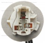
Inside the socket, you should see 4 contacts, I believe. 2 if those will be attached to the ground wire. Each of the other two will be connected to their corresponding power wires. So to figure out which wire on your new socket pigtail is the ground wire, you will need to use the meter to figure out which wire is connected to 2 of the inside contacts. It is a process of elimination. Your socket may look slightly different from the ones on Ron's picture above. But the contacts must be arranged like that because it is an industry standard. It has to be that way for the standard 3157 bulb to work.
 
My socket does not look like Ron's at all. I tried to find a diagram online for the S547 socket like Ron posted. Here is a photo below
imagehandlergs.ashx.jpeg
 
Last edited:
Ground looks to be the top connection in above picture
If has TWO connections for the bulb
 
Ok. I kinda' thought this one had the 4 contacts like you and Eric were saying. The top connection you speak of is kind of hard to see in that dark recess.

I think I already did this 'process of elimination' thing without really being aware of it.

But I'll probe all 3 wires with all 4 contacts again and I'll let you know the results
 
I probed all 3 wires with all 4 socket contacts. And this is what it came back with.

The top contacts Ron mentioned were the ONLY contacts in the socket that returned TWO readings of 0.000 ohms. And it did this for the center pigtail wire.
Am I making progress?
 

Sponsored Ad


Sponsored Ad

TRS Events

Member & Vendor Upgrades

For a small yearly donation, you can support this forum and receive a 'Supporting Member' banner, or become a 'Supporting Vendor' and promote your products here. Click the banner to find out how.

Latest posts

Recently Featured

Want to see your truck here? Share your photos and details in the forum.

Ranger Adventure Video

TRS Merchandise

Follow TRS On Instagram

TRS Sponsors


Sponsored Ad


Sponsored Ad


Amazon Deals

Sponsored Ad

Back
Top