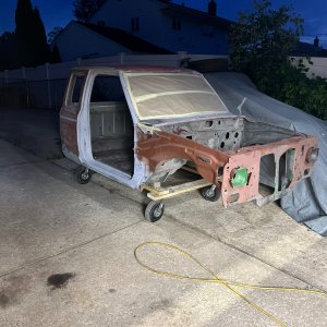
I hope you're right. I've read and seen conflicting info; some information sources state that the rpms will be different between a 4 and 6 cylinder engine, while other sources state it should be plug and play as you've said.
Here's an outtake of an AI Overview when I searched for info just now:
Quote- "The 1998–2003 Ford Ranger dash clusters use the same plug-and-play wiring design. Both your original 2.5L 4-cylinder engine and the 3.0L V6 from the 1998 donor vehicle send the exact same RPM signal pulse directly from the Powertrain Control Module (PCM) to the cluster. Because the tachometer reads these pulses rather than being mechanically calibrated for a specific engine type, it will display the correct RPMs."
Like I said, I hope this it right. I reckon I'll find out once it's delivered and I put it in the truck. I'll check it with my Blue Driver scan tool after installation.
You're right, the anti slosh module can be another issue but hopefully it will be the same. The gas gauge is already inaccurate since I replaced the OEM Motorcraft fuel pump assembly with a Delphi assembly last year.
It always reads around 5 gallons low but not consistently so an anti slosh module malfunction on top of that wouldn't be cool at all lol.
Thank you for the reply.
I haven’t read this whole thread, but I get the gist of if after
@scotts90ranger spoke up and tuned me in.
I did a moderate amount of research, and the conclusion I came to was also that it should be plug & play from Ranger to Ranger. If you think about it, he sent me a cluster from a 5.0 V8 explorer, and it pretty much just worked when I put it in.
I’ll cut to the chase on a few things, especially if you’re going to change over your odometer. This is a summary of several people’s good knowledge and help and my experience when I was doing it this past couple weeks.
1. Before you pull the speedometer needle off!!! When you pull the gauges out of the circuit board and housing, looking from the back, there are four close-in solder points close to the servo motor (bell looking thing) at the center of the needle. Using a 1.5 V battery, put the positive on the top left and the negative on the bottom right, looking from the back. Lay the speedo flat so it is facing the ceiling. Let it sit and level out, and record what it’s reading. It should be around 40 mph.
2. Pull the needle. If you don’t have a plastic fork pry tool, just use a fork. You may want to put a piece of masking tape on the back of the fork where it’s going to touch the face so you don’t scratch the face.
3. Take the three screws out of the back and swap the odometer/speedo.
4A. Before you put the needle back on, reconnect the 1.5 V battery with the speedo facing the ceiling. Btw, I have a couple of pieces of plywood, cut to rest on the bottom of my vice between the jaws, so I can put fine things in there without crushing them. Take the needle and very carefully drop it on - without pressing it on - and move the needle to the same MPH. I’m not exactly sure how that gizmo works, but it may wander around a little bit, but it will settle out.
4B. You want it to settle out before you push the pin on. When you push the pin on, don’t push it down all the way, just enough so that it grabs the needle. Once you push it on, make sure it’s still reading the same MPH. If not, pull it and do it over.
4C. While it’s still laying flat, after you push the pin on, just gently using your finger, push the needle lower and and see if it returns to the same spot. Then push it higher and see if it returns to the same spot. When I did it, when I pushed it lower, it would come back, and when I pushed it higher, it would come to 2-3 mph higher. I left it at the lower setting.
5. Tighten the pin puncher points before you put your gauges back into the circuit board/assembly. I used a right angle pick, you can buy four for $1.99 at Harbor Freight, and I gently inserted the point in the fold of each side of the pin pinch points, and very gently twisted it to close the gap between those jaws. You do this to make sure you’ve got a solid connection when you push the gauges back on. I did a very quick spin on each one of the connection pins on the back of the gauges with a piece of fine Emory paper. When I pressed them in, I actually put them in, pulled them up a little bit, pushed them in, a few times to make sure I had a good contact.
6A. Check all your lightbulbs. If you look at the back of the circuit board, the big twisted lights are your background illumination. Check that all of them are working. Remember if you upgrade to LEDs, there is a positive side and a negative side. If you use the old incandescent bulbs, it doesn’t matter. However, either way, I usually use a pick or a tiny screwdriver to pick up the brass contacts on either side of the holder to make sure they make a solid connection
6B. The gauge clusters are universal for many different set ups on Ranger trucks. If you use a magnifying glass and you look at the back of the circuit board, what each bulb does is actually written out. My Ranger is it 2WD, so I pulled out all of the 4WD stuff. There was a security bulb that is a little bit different, I don’t have a security system, so I pulled that and I put a little piece of masking tape gently over the hole. Then I went one by one with all the rest of the little bulbs, and after checking them, on every single one, I bent the brass contacts up a hair.
6C. I’m an old fart, at that age where sometimes I ride around town with my turn signal on. So on this truck, and actually on a couple other cars and trucks I’ve had, I upgrade the turn signal bulbs to the brighter LEDs. They are literally four or five times or more as bright, so when they’re flashing, you can really see them, but not so bright they’re distracting. Remember there’s a positive and negative side, they have to be inserted properly. I’ve never done it, but if there’s another light you want to make sure you can see, put an LED in that one too.
7. Clean up the contacts where the three multifunction plugs plug in the back. BE VERY CAREFUL AND VERY GENTLE. The contact points are just part of the circuit board membrane that are folded into the back of the cluster. Make sure they are all laying flat in the right place. I would never spray anything on that flimsy plastic circuit board, but I have put a little contact cleaner from a spray can into a bottle cap, and then I’ve used a Q-tip to grab some up, I squeeze out 90% of what’s on the Q-tip so it’s almost dry, and I gently rub the contact surface. You have to be really careful you don’t screw up the circuit board. You may want to practice on a junk cluster.
8A. The assumption that the speedo will read correctly is a bad assumption, in my experience. Some guys do the 1.5v volt trick and it comes up dead on the money, I had to put my cluster in and out four or five times before I got it right. So starting with the procedure in item 4, I would put the cluster in without even putting the clear lens on it, and put the dashboard bezel on with a couple of screws, just enough so you can test drive it down the road.
8B. I have three of the flashing radar/speed warning signs in front of schools within spitting distance of my house. If you go outside of school hours, the speed limit is usually something like 35 miles an hour. So you can drive by at 20 mph and see what the speedometer reads, and then carefully go past again at maybe 40 mph and see what the speedometer reads. My first try I was moving 7 mph faster than the speedometer was reading. After I did the procedures on the bench above, the second time I was 4 mph faster. Third time was the Charm. On the bench, with the battery attached, facing the ceiling, let the needle settle in, pull it off, and simply put it in adjusted for the MPH difference. Again, I had to do it twice, which is why I recommend doing your test drives before you put the whole thing back together.
9. When it was finally reading right, I obviously took the cluster out, cleaned it, and put it all back together with the lens. On the three multifunction plugs, I pushed them in and out two or three times each, very carefully, to make sure they made a good contact. Between the cluster and the different bezels, I had Philips screws, 8 mm, 7 mm, and I think a hairpin. I changed them all to Philips screws, except the two that hold the hood release in the center underneath the steering column. On those two, you just can’t see the holes where they’re going, so it’s easier to put in a hex head screw, sitting in a socket pointing upward, then trying to balance a screw.
10. Before I go down the interstate at 100 mph, I would do the School radar check a couple more times. Placing that needle is a very finicky thing, especially if you’ve got my ancient shaky hands.
That’s what I learned, and again, not that I’m so smart, I had a lot of help from some really good guys when I was figuring it out. Again, this is a step by step summary of what worked for me. I hope it helps.


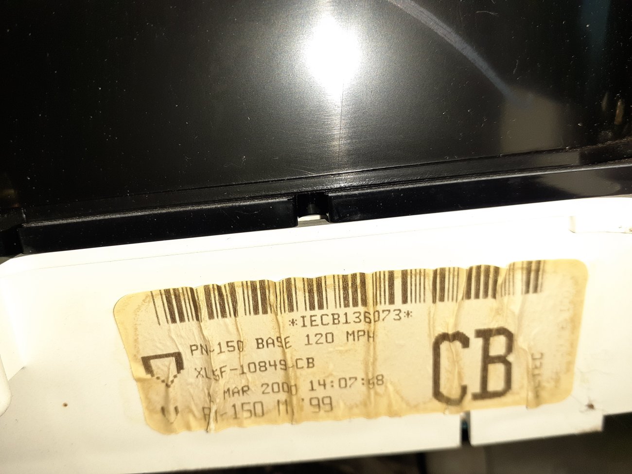


 Bad Rick, Baaad.
  J/k
J/k