
Introduction
This article covers the TFI (Thick Film Ignition) Module used on the Ford 2.8L/2.9L V6 engines and how to test it. These modules are prone to go bad causing the engine to stall, dye, sputter or not start when hot but runs when it cools off. The engine won’t run at all if it completely fails. The biggest culprits are heat or a wire grounding out. Problematic TFI’s can give off codes 14 (PIP) and 18 (SPOUT).
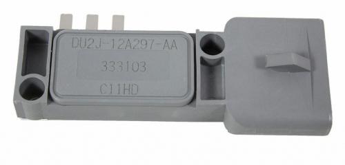
Ford 2.8L/2.9L TFI Module
Quick Checks
Technical Service Bulletins (TSBs) pertaining to the ignition system:
- TFI Stall NO Start – TFI Module Diagnosis and Sealing: This bulletin addresses loss of module ground due to salt and moisture entering a module mounting screw.
- TFI Engine NO Start/Stall at Idle – New Ignition Module: This TSB talks about an internal short-circuit in some model TFI modules.
- Drivability Concerns – Moist EEC-IV Connectors: This bulletin asks the tech to check for unsealed EEC-IV connectors and check for moisture or corrosion.
Wiring:
Always check your wiring. Here is a picture of the SPOUT (Spark Output signal) wire that was grounding out.
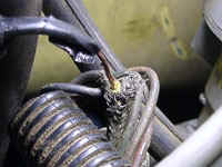
The yellow spark output signal wire is without a section of insulation. This section happens to run through a shield ground that provided a convenient ground source for the SPOUT signal. Just the right bump in the road or vibration from the engine would provide a path of lesser resistance for the SPOUT signal, killing the coil trigger.
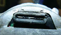
This is where the TFI Module plugs in to the distributor to get the PIP signal. Notice the defective insulation.
Heat Is Your Enemy!
The top three leads (for PIP signal) can lose continuity with the back plate (ground) on the module when the unit is hot. You should consider a remote mounted TFI. If your TFI is failing from heat, it can give off computer codes 14 (PIP) and 18 (SPOUT).
General Information
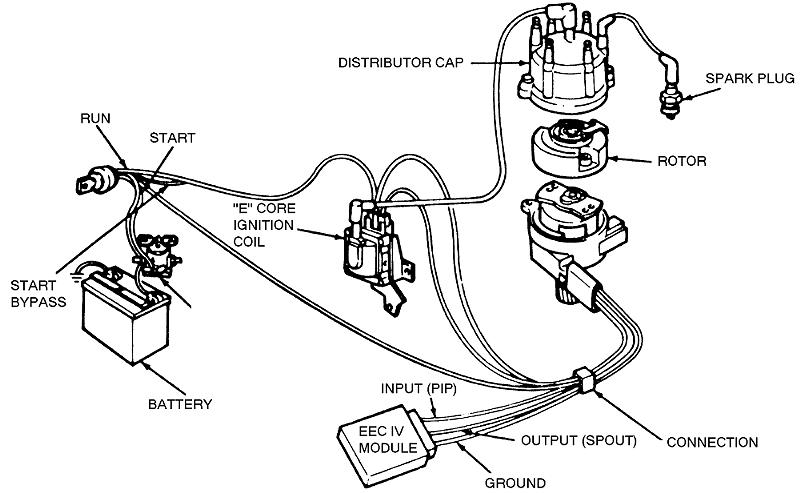
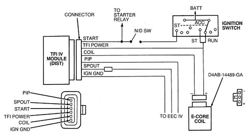
The TFI-IV distributor ignition system consists of the following components:
- Thick Film Ignition (TFI) modules
- Distributor
- Camshaft Position (CMP) sensor
- Ignition coil
The distributor ignition system designed by Ford has two distinct configurations. The first configuration is known as the distributor mounted system, because the TFI is mounted directly on the distributor housing. The second configuration is known as a remote mount system, since the TFI is mounted on the engine or front fender apron.
The distributor used by this system is sealed and houses the CMP sensor. The distributor does not utilize vacuum or centrifugal advance mechanisms; the ignition timing is automatically controlled by the Powertrain Control Module (PCM) and the TFI.
Ford calls this electronic ignition the Thick Film Integrated-IV (TFI-IV) ignition system. The TFI module is also known as the Ignition Control Module (ICM) which reports engine position and rpm to the PCM. The PCM then determines the proper spark timing and advance, and returns a reference signal to tell the TFI module to switch the coil, thereby by creating a spark. The PCM used on these vehicles is referred to by Ford as the Electronic Engine Control-IV (EEC-IV) module.
System Operation
The CMP sensor, housed inside the distributor, responds to a rotating metallic shutter mounted on the distributor shaft. This rotating shutter produces a digital Profile Ignition Pick-up (PIP) signal, which is used by the PCM and TFI to provide base timing information, determine engine speed (rpm) and crankshaft position. The distributor shaft rotates at one-half crankshaft speed; therefore, the shutter rotates once for every two crankshaft revolutions.
The TFI functions in either one of two modes: push start or Computer Controlled Dwell (CCD). The push start mode allows for increased dwell, or coil on time, when starting the engine. During this mode, the TFI determines when to turn on the ignition coil based on engine speed information. The coil is turned off, thereby firing, whenever a rising edge of a SPark OUTput (SPOUT) signal is received. The SPOUT signal is generated by the PCM, and provides spark timing information to the TFI. During the push start mode, the SPOUT signal only indicates the timing for coil firing; the falling edge of the SPOUT signal is ignored. Despite the name, the push start mode is also enabled during engine starting with the ignition key.
Do not attempt to push start a vehicle equipped with an automatic transmission.
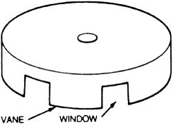
The rotary armature has open areas called windows and tabs called vanes
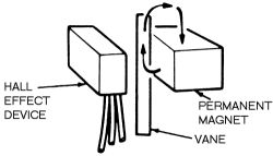
The vane interrupts the magnetic field passing through the Hall effect device
During the CCD mode, both edges of the SPOUT signal are utilized. The leading edge of the SPOUT signal is used by the ICM in the same manner as during the push start mode. The falling edge of the signal is generated to control the timing for turning the ignition coil on (the TFI no longer controls this function as during the push start mode). During the CCD mode, the coil on time, or dwell, is entirely controlled by the PCM through the SPOUT signal.
In the event that the SPOUT signal from the PCM is disrupted, the TFI will use the PIP signal from the CMP to fire the ignition coil, which results in a fixed spark angle and dwell.
Diagnosis & Testing
Service Precautions
- Always turn the key OFF and isolate both ends of a circuit whenever testing for shorts or continuity.
- Never measure voltage or resistance directly at the processor connector.
- Always disconnect solenoids and switches from the harness before measuring for continuity, resistance or energizing by way of a 8-volt source.
- When disconnecting connectors, inspect for damaged or pushed-out pins, corrosion, loose wires, etc. Service if required.
Preliminary Checks
- Visually inspect the engine compartment to ensure that all vacuum lines and spark plug wires are properly routed and securely connected.
- Examine all wiring harness and connectors for insulation damage, burned, overheated, loose or broken conditions. Ensure that the TFI is securely fastened to the front fender apron.
- Be certain that the battery is fully charged and that all accessories are OFF during the diagnosis.
Make A PIP Tester
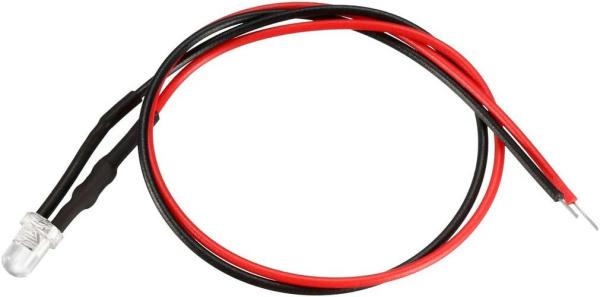
The LED is an automotive LED with a built-in resistor. Soldered a wire with an alligator clip to the end of each wire. Red to red and black to black. The LED is polarity specific. This means that voltage will only pass from the LED’s red lead to its black lead. This also means that you have to pay close attention to the testing instructions so that your connections are correct.
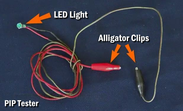
Below you can see a prewired LED light from Amazon that has a resistor in the red wire. You could use this for your test by connecting a test lead with an alligator clip at each end to each of these wires instead of soldering a wire and alligator clip to it.
Test Procedures
Perform the test procedures in the order in which they are presented here.
Ignition Coil Secondary Voltage Test
Coil Voltage Test #1 – Crank Mode
1 – Connect a spark tester between the ignition coil wire and a good engine ground.
2 – Crank the engine and check for spark at the tester.
3 – Turn the ignition switch OFF.
4 – If no spark occurs, check the following:
a. Inspect the ignition coil for damage or carbon tracking.
b. Check that the distributor shaft is rotating when the engine is being cranked.
c. If the results in Steps a and b are okay, go to Test #4.
5 – If a spark did occur, check the distributor cap and rotor for damage or carbon tracking. Go to the Coil Voltage Test #2.
Coil Voltage Test #2 – Run Mode
1 – Fully apply the parking brake. Place the gear shift lever in Neutral (manual transmission) or Park (automatic transmission).
CAUTION – Failure to perform this step may result in the vehicle moving when the starter is subsequently engaged during the test.
2 – Disconnect the S terminal wire at the starter relay. Attach a remote starter switch.
3 – Turn the ignition switch to the RUN position.
4 – Using the remote starter switch, crank the engine and check for spark.
5 – Turn the ignition switch OFF.
6 – If no spark occurred, the problem lies with the wiring harness. Inspect the wiring harness for short circuits, open circuits and other defects. Go to Test #3.
7 – If a spark did occur, the problem is not in the ignition system.
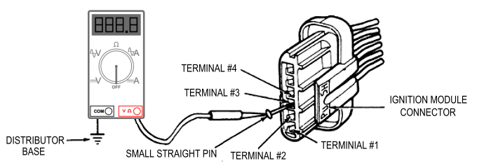
Wiring Harness Test #3 – Voltage Check
1 – Separate wiring harness connector from ignition module. Inspect for dirt, corrosion and damage. NOTE: Push connector tabs to separate.
2 – Verify that the wire to the S terminal of starter relay is disconnected.
3 – Attach negative (-) VOM (Volt Ohm Meter) lead to distributor base.
4 – Measure battery voltage.
5 – Following the appropriate table below, measure connector terminal voltage by attaching VOM (Volt Ohm Meter) to small straight pin inserted into connector terminal and turning ignition switch to position shown.
CAUTION – DO NOT allow straight pin to contact electrical ground.
|
TFI Without CCD |
||
|
Connector Terminal |
Wire / Circuit |
Ignition Switch Test Position |
| #3 | Run Circuit | Run and Start |
| #4 | Start Circuit | Start |
|
TFI With CCD |
||
| Connector Terminal | Wire / Circuit |
Ignition Switch Test Position |
| #3 | Run Circuit | Run and Start |
6 – Turn ignition switch to Off position.
7 – Remove straight pin.
8 – Reconnect wire to S terminal of starter relay.
9 – Was the value at least 90 percent of battery voltage in each case?
a. – If ‘Yes’, replace TFI module.
b. – If ‘No’ then:
1 – Inspect for faults in wiring harness and connectors.
2 – Check for damaged or worn ignition switch.
Distributor Hall Effect Test #4
1 – Place the transmission shift lever in the ‘Park’ position (A/T) or Neutral (M/T) position and set the parking brake.
CAUTION – Failure to perform this step may result in the vehicle moving when the starter is subsequently engaged during the test.
2 – Disconnect the harness connector from the TFI module and connect the TFI tester (The PIP tester you made above with an LED light).
3 – Connect the red lead from the tester to the (+) positive side of the battery.
4 – Disconnect the wire at the S terminal of the starter relay and attach remote starter switch.
5 – Crank the engine using the remote starter switch and note the status of the two LED lamps watch for the light to blink.
6 – Remove the tester and remote starter switch.
7 – Reconnect the wire to the starter relay and the connector to the TFI.
8 – Did the PIP light blink?
a. – If ‘Yes’, go to Test #6.
b. – If ‘No’, remove distributor cap and verify rotation. If OK, go to Test #5.
TFI Module Resistance Test #5
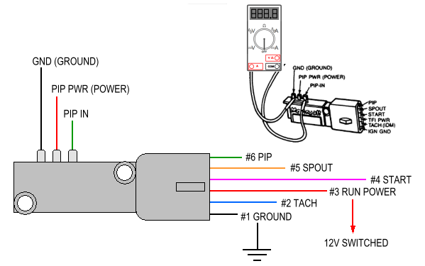
1 – Remove the TFI from the distributor or the front fender apron.
2 – Measure the resistance between the TFI terminals as shown below:
a. – GND – PIP IN: should be greater than 60 ohms.
b. – PIP PWR – PIP IN: should be less than 2,000 ohms.
c. – PIP PWR – TFI PWR: should be less than 200 ohms.
d. – GND – IGN GND: should be less than 2 ohms.
e. – PIP IN – PIP: should be less than 200 ohms.
3 – If any of these checks failed, replace the TFI with a new one.
TFI Module Test #6
1 – Use status of Tach light from Test #4. If ‘Yes’, then go to Test #7.
2 – Did the Tach light blink? If ‘No’, replace TFI module and check for spark using the method described in Test #1. If spark was not present, replace the coil also.
System Test #7
1 – Disconnect the pin-in-line connector near the TFI.
2 – Crank the engine
3 – Turn the ignition switch OFF.
4 – If a spark did occur, check the PIP and ignition ground wires for continuity. If okay, the problem is not in the ignition system.
5 – If no spark occurs, check the voltage at the positive (+) terminal of the ignition coil with the ignition switch in RUN.
6 – If the reading is not within battery voltage, check for a worn or damaged ignition switch.
7 – If the reading is within battery voltage, check for faults in the wiring between the coil and TFI module terminal No. 2 or any additional wiring or components connected to that circuit.
Spark Timing Advance Test #8
Spark timing advance is controlled by the EEC system. This procedure checks the capability of the ignition module to receive the spark timing command from the EEC module. The use of a volt/ohmmeter is required.
1 – Turn the ignition switch OFF.
2 – Disconnect the pin-in-line connector (SPOUT connector) near the TFI module.
3 – Start the engine and measure the voltage, at idle, from the SPOUT connector to the distributor base. The reading should equal battery voltage.
4 – If the result is okay, the problem lies within the EEC-IV system.
5 – If the result was not satisfactory, separate the wiring harness connector from the ignition module. Check for damage, corrosion or dirt. Service as necessary.
6 – Measure the resistance between terminal No. 1 and the pin-in-line connector. This test is done at the ignition module connector only. The reading should be less than 1 ohms.
7 – If the reading is okay, replace the TFI module.
8 – If the result was not satisfactory, service the wiring between the pin inline connector and the TFI connector.
Our Old Testing Procedure
STEP 1
Determine if the engine is getting fuel. If injector is fueling chances are the TFI electronics are ok. If the electronics fail the fuel system shuts down except for about 20 seconds of start of cranking. If no fueling or if it quits after 20 seconds of cranking go to step 2.
STEP 2
Check for spark at one of the spark plugs. If spark is found, you may have a fuel system problem. If spark is not found, check for spark at the coil wire. If you have spark, you may have a bad rotor, cap, or wires. If you still have no spark, unplug the harness at the TFI module. With key off, there should be no voltage present at any terminals of the harness. With key in the run position there should be voltage at the “TFI POWER RUN” and the “TACH IDM (COIL NEGATIVE)” terminals. Pull the small wire off the starter solenoid so engine will not crank. Have an assistant try to crank the engine. There should be voltage at “TFI POWER RUN, TFI POWER CRANK (START SIGNAL IN), and TACH IDM (COIL NEGATIVE)” terminals. If there is not voltages present, there is a possible wiring problem. If voltages are ok, go to step 3.
STEP 3
With coil wire removed to watch for spark, place ignition key in the run position. Momentarily touch a jumper wire from “TACH IDM (COIL NEGATIVE)” terminal of the harness to a good ground. Spark should jump every time the jumper is grounded. Do not ground the jumper for more that a couple of seconds. If no spark is found, make sure that with the key in the run position there is voltage at one of the coil terminals. If voltage is present, the coil may be bad, go to step 4. If spark is found, the problem may be the TFI module or the PIP (profile ignition pickup or reluctor in the distributor) so go to step 5.
STEP 4
We should now test the coil. Use an ohm meter and probe the resistance of the two small terminals, and you should find 0.3 to 1.0 ohm. If the resistance is not ok, it may be a bad coil. If the resistance is ok, probe one small terminal and the coil wire terminal. Resistance should be 8000 to 11,500 ohms. If the resistance is not ok, replace coil. If the resistance is ok, go to step 5.
STEP 5
Testing the pickup coil (PIP) in the distributor is not an easy task, and best to test the TFI module first, then replace the pickup coil (PIP) if the TFI module tests ok. I have seen very few pickup coils on Ford TFI systems go bad. Test the TFI module according to the chart below. These values may be valid only on an OEM module, but may apply to aftermarket.
TFI Terminals to jump Resistance (OHMS)
| HALL EFFECT GROUND | HALL EFFECT POWER | PIP | |
| PIP out | 12.8K | 1.2K | 100 |
| SPOUT in | 17.4K | 5.8K | 4.7K |
| START SIGNAL in | 1000 | 12.6K | 13.7K |
| RUN POWER in | 11.5K | 100 | 1200 |
| COIL NEGATIVE | 4.2K | 15.8K | 16.9K |
| IGNITION GROUND | 0.0 | 11.6K | 12.7K |
| HALL EFFECT POWER | 11.5K | ||
| PIP | 12.6K | 1100 | |
| DISTRIBUTOR BASE | 0.0K | 12K | 13.1K |
Helpful Links:
TFI Worksheet (Strongly recommend you print this worksheet)
Ford TFI Module Litigation Settlement
Related Articles
Remote Mounted TFI Ignition Module
Last Updated:
About The Author
Jim Oaks is the founder of TheRangerStation.com, the longest-running Ford Ranger resource online since 1999. With over 25 years of hands-on experience building and modifying Ford Rangers — including magazine-featured builds like Project Transformer — Jim has become one of the most trusted authorities in the Ford Ranger off-road and enthusiast space.
Since launching TheRangerStation.com, Jim has documented thousands of real-world Ranger builds, technical repairs, drivetrain swaps, suspension modifications, and off-road adventures contributed by owners worldwide. TheRangerStation.com has been referenced in print, video and online by enthusiasts, mechanics, and off-road builders looking for practical, and experience-based information.