
Difficulty: Varies depending on complexity of system chosen
Time to Install: Varies depending on complexity of system chosen
Disclaimer: The Ranger Station.com, The Ranger Station.com Staff, nor the original poster are responsible for you doing this modification to your vehicle. By doing this modification and following this how-to, YOU, the installer, take full responsibility if anything is damaged or messed up. If you have questions, feel free to PM the original poster or ask in the appropriate section of The Ranger Station.com forums. ALSO, at the time of this writing, neither TheRangerStation.com or the author are sponsored by any specific companies or brands that my be mentioned herein.
Tools Needed:
Various general hand tools, including, but not limited to wrenches, screwdrivers, drill, etc.
Various electrical hand tools, including, but not limited to wire cutter, wire stripper, crimper, soldering iron and supplies, heat gun, multimeter
Parts needed:
Varies depending on type of system chosen for installation.
I. Introduction
So, you want an auxiliary electrical power supply for your RBV. There are many choices to be made. The system can be as simple or extensive as you want. Hopefully, this article will help you navigate the process – defining your needs, choosing the right type of system and designing it to fit your needs, your truck and your budget.
II. Goals: What are your needs?
A. What equipment do you need to power?
- Camp Lighting
- Refrigerator
- Charging equipment batteries
- Fans
- Air compressor
- Air pump to blow up air mattresses
- Portable appliances
B. How often will you need this system?
- Occasional camping
- Tailgating at sporting events
- Frequent or extended camping trips “Overlanding?”
- Just once or twice a year
C. Other Details
- Do you need portability? Ie; move system from one vehicle to another or into the house?
- Do you want it built into a vehicle more permanently and hidden away?
- Will you need 120Volts AC power (like the power in your house)
- Do you need the ability to recharge the system batteries independently of running the vehicle engine or plugging into “shore power”? Shore power is a term commonly used to describe plugging a cord into an AC outlet as you might do in a campground or at home.
- What is your budget?
- What are your skills? Will you be installing the system yourself? Or must you hire someone to build and install it?
III. System Design Choices
A. There are many ways to approach this. That is why you need to consider the things mentioned above. Here is a basic list of many system designs available. This is not an exhaustive list. There are always variations and hybrid designs options.
| System | Description | Pros | Cons | Approx. Cost |
|---|---|---|---|---|
| Dual Vehicle Batteries | Second battery in parallel with vehicle’s starting battery. | Inexpensive, easy install. | Risk of “no start” if discharged too far. | $ |
| Power Stations (Store-Bought) | Self-contained units (Jackery, Bluetti, etc.) | No installation, portable, plug-and-play. | Limited capacity, requires recharging source. | $$–$$$$ |
| Separate Battery Bank | Custom-built, independent system. | Inexpensive, flexible design. | Requires recharging source, DIY complexity. | $$ |
| Battery Bank with Solar | Separate battery system with solar panels. | Self-charging, renewable. | Custom design required, sunlight dependent. | $$–$$$$ |
| Full System (Integrated) | Battery bank integrated with vehicle charging system. | Charges while driving and from solar. | Newer vehicles may require DC-DC charger. | $$$–$$$$$ |
| Full System + Inverter (AC Power) | Full system plus inverter for 120V AC output. | Runs household devices, flexible use. | Takes more space, more cost. | $$$$$ |
B. One of the main things you need to understand in deciding what SIZE of a system you need, is the concept of “Amp-Hours (AH)”. All electrical equipment draws current, measured in Amps. So, if an item draws 3 Amps continuously for 2 hours, it will use 6AH of electricity. Amps X Hours = Amp-Hours . Batteries and power stations almost always have an Amp-hour rating or Watt-hour rating on the nameplate, in the owners manual or on the manufacturer’s website. Equipment that uses electricity will be labeled to indicate how many amps it requires. So you can calculate how many amp-Hours it will require. Electrical devices may be rated in “Watts” instead of Amps. “Watts” are a measurement of power used. For our purposes here, we can calculate Amps if we know the Watts and the Voltage the device is operating on, most often 12 Volts in common automotive applications. So, Watts = Amps X Volts or, conversely, Watts / Volts = Amps. So, for a 60-Watt device, 60 Watts / 12 Volts = 5 Amps. We can also talk about Watt-Hours, which would be the number of watts used in an hour. Your home electrical bill is calculated on “Kilowatt-Hours (KWH)” which is thousands of watt-hours.
C. So, to decide what size of a system you need, you need to plan what equipment it will serve and how much time each piece of equipment will be using the electricity. Always round up and even add extra capacity for future growth or unplanned additions. Here is an example;
| Device | Amps / Watts | Hours of use per day | Amp-Hours (AH) |
|---|---|---|---|
| Exterior camp lights | 2.5 A | 3 hrs/day | 7.5 AH |
| Interior lights | 2 A | 2 hrs/day | 4.0 AH |
| Charging cellphones | 0.5 A | 2 hrs/day | 1.0 AH |
| Charging laptop computer | 1.5 A | 1.5 hrs/day | 2.25 AH |
| Refrigerator / Freezer (84 W max, ~42 W eco) | ≈42 W → ≈3.5 A @ 12V | 24 hrs/day | 84.0 AH |
| Fan | 1 A | 7 hrs/night | 7.0 AH |
| Total per day | 105.75 AH | ||
So, this translates to; 105.75 Amp-Hours per day. Let’s round that off to 106AH for convenience. If you need to run these loads for a 24hr period without re-charging your battery from another source (vehicle alternator/solar charger/external battery charger) then you will need a battery source that can provide in excess of 106 Amp-Hours in between recharging sessions. As an example, in my vehicle, I built a system with two 100AH Marine batteries in parallel with my 65AH vehicle battery for a total capacity of 265AH. During the daytime, my solar panels can provide charging up to 200 Watts per hour depending on the sunlight available. During the day, the batteries are re-charged by the solar while also supplying the system loads. Or the batteries can be re-charged and system loads supplied by the vehicle alternator if the system is connected to it in some way.
IV. Technologies
A. Power storage – batteries. Batteries are the primary way to store electrical power. There are many technologies available. Some are better than others. Here is a very brief and simple description of each. One important thing to remember is that if you plan to use 2 or more batteries in parallel for greater capacity, they need to be the same type, same size and same age. Otherwise, problems will develop, and performance will suffer.
a. Lead Acid Batteries – conventional, old-school car battery technology. Probably least expensive. Easy to use. Should not be submerged in deep water crossings. Can not handle being deeply discharged. Good in colder climates.
b. Lead Acid Marine batteries – Old-school technology, But… They can be deeply discharged, giving greater capacity. They are sealed in such a way that they can handle temporary submersion. This gives greater flexibility in where you can mount them in the vehicle. Very robust and durable. Good in colder climates.
c. AGM Batteries – These are similar to Lead Acid batteries. However, instead of the acid mixture sloshing around freely within the battery, it is absorbed into fiberglass matting material. These batteries are much better for vehicles that see extreme angles in usage because they won’t spill. They are good in colder climates. AGM batteries prefer more specialized charging methods, but some are suitable for use in normal vehicle charging systems and will hold up fine in the types of auxiliary systems we are discussing. They are NOT good for high discharge rates. In other words, don’t use these for primitive “Trail Repair Welding” situations where you just hook up some booster cables, put a welding rod in one clamp and start welding. Optima is one common brand of AGM vehicle battery.
d. Lithium Ion & LiFePo4 & LiFePo4 Hybrid Batteries – These batteries are much newer technology. They are very “power dense” meaning they pack more energy into smaller packages. These are usually lighter, also. Some of these are more prone to losing capacity at low temperatures. However, there are some LiFePo4 batteries that I will call “Hybrids” that have Capacitor technology and smart electronics built in that are reputed to be excellent for low temperatures and protect themselves from being discharged too far, thereby leaving you with power to start your engine. (charging requirements?)
e. Calcium Batteries – Lead Acid batteries with Calcium added to their plates. These are supposed to be great for high temperatures and other harsh offroad conditions.
f. Power Banks / Power Stations – Self-contained battery sources with various output power supplies built-in. These usually have Li-Ion or LiFePo4 batteries and contain everything needed so you can charge them from your car or Household AC power. They have many options including 12Volt DC power ports, USB charging ports, sometimes 120Volt AC receptacles and even solar panels for recharging themselves. Very handy all-in-one solution to make life easy. More details later.
B. Solar Panels
a. Monocrystalline – High efficiency and long life. Made from a single crystal structure. More expensive.
b. Polycrystalline – Balance of cost and efficiency. Made of multiple crystal structures. Budget-friendly
c. Thin Film panels – Lightweight and often flexible. Shortest lifespan. Sometimes marketed for applications where they need to bend slightly to mount directly on things like vehicle hoods that are curved.
d. PERC (Passive Emitter & Rear Cell) – Newer technology emerging. Higher efficiency. Adds a layer to capture more sunlight. I believe I saw these recently at an Overland Expo. The company had them mounted so that they could capture light reflecting off the vehicle and hitting the bottom of the panels.
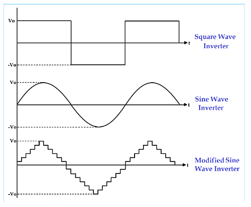
C. Inverters. Inverters are devices that take DC voltage (like battery voltage) and turn it into 120volt AC power like what you use at home. There are 3 major types. The difference is the quality of the AC power they produce. AC voltage cycles from positive to negative 60 times per second, in the U.S. As it does so, if we could see it, the voltage value would trace a sinusoidal wave pattern over time – a sine wave. Rotating generating equipment makes a perfect sine wave. But inverters have to create this shape electronically. The circuits to do this are complicated. So, lesser quality inverters use simpler circuits to “approximate” the sine wave. Here are the 3 types. Square wave is the worst quality, and the pure sine wave is the best quality.
One other thing. Remember to plan out the AC portion of your system just like we do the DC portion. What will you be powering with your inverter? A common microwave uses 1100 – 1500 watts. My Milwaukee M18 battery charger draws 2.1Amps which is 252 watts. So I would need a 300watt inverter to run just that charger. That will be a little over 21 DC amps on my Auxiliary electrical system. Decide what your loads are and plan accordingly.
Inverters will have 2 power ratings. “continuous” and “peak”. Use the continuous rating for designing your system and round your numbers up about 10%. The peak rating is for brief momentary spikes in power usage.
Motors do this commonly. So, if you turn on a drill motor or a blender, in the first few milliseconds, the current or power usage will be roughly 10-20 X’s higher than the rated continuous current. But it is for such a short duration, that we can almost ignore it. This is one reason; we always design a circuit with a breaker or fuse rated at 125% of the expected load of the circuit. It gives us a safety buffer for unexpected current spikes.
a. Square Wave – These are becoming less prevalent since better electronic devices have come down in price. These create a voltage pattern that works ok with simple devices like universal motors. But it can be harmful to more sensitive devices. Other devices may not work at all. Stay away from these. Avoid them at all costs.
b. Modified Sine Wave – These simulate a sine wave using square waves of differing amplitudes and/o time intervals. Many devices will work with this kind of power. But they will work less efficiently and use more power.
c. Pure Sine Wave – These develop the closest sine wave form that can be made without using a rotating generator. Since all AC devices are designed to use this kind of power, this is what works best. Your devices will be more efficient and use (waste) less power if you can use a pure sine wave inverter.
D. Other Devices
a. Solar controllers – These are necessary when you introduce solar panels into your system. They take the voltage from your solar panels and use it to charge your batteries or directly supply loads. They are programmed to stop when the sunlight on the panels is insufficient for battery charging. Some may even have different types of charging programs such as normal charge and float charge (maintain). Some may have built-in displays. But most, these days seem to have Bluetooth or WiFi connectivity to communicate with your phone or tablet. Through the app, you can monitor solar panel voltage, battery voltage, charging current and more.
b. DC-DC chargers – These are devices that use one DC source, like your vehicle battery to charge another battery. You can install one of these between your vehicle battery and your auxiliary battery(s) to allow the vehicle to charge the auxiliary battery. They may have various features such as Bluetooth or WiFi connectivity to allow remote monitoring and programming setpoints. They may even have alarms to notify you when certain events happen.
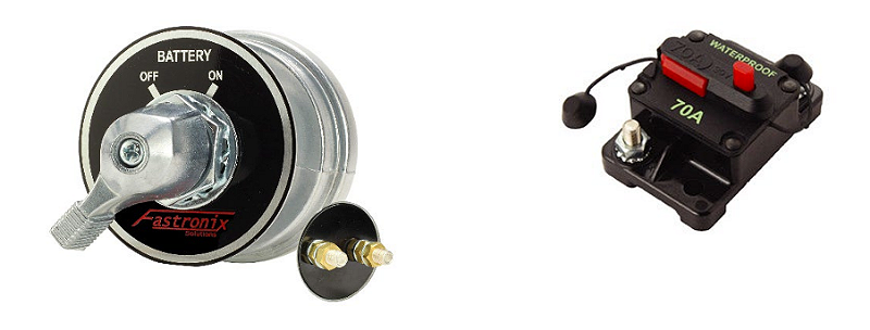
c. Battery Disconnects – Always use some kind of disconnecting means at your batteries. You can buy battery disconnect switches. You can also use a circuit breaker, if it has a way for you to manually open the breaker quickly and easily, like the one below. This is a safety device to open the circuit quickly in case of emergency. (Battery disconnect on left, Circuit breaker on right)
d. Monitoring and switching Components
i. Battery Monitors – Used to monitor battery voltage, current and state of charge (how much power is remaining). Some have built-in displays, and some interact with computer devices via WiFi or Bluetooth through an app.
ii. Automatic Control Relays – Electronic devices used to connect or disconnect components like batteries when certain preset conditions exist. One use is to disconnect your auxiliary electric system from the main vehicle system when battery voltage gets down to a certain level, thereby ensuring that you will have enough vehicle battery power to start the engine.
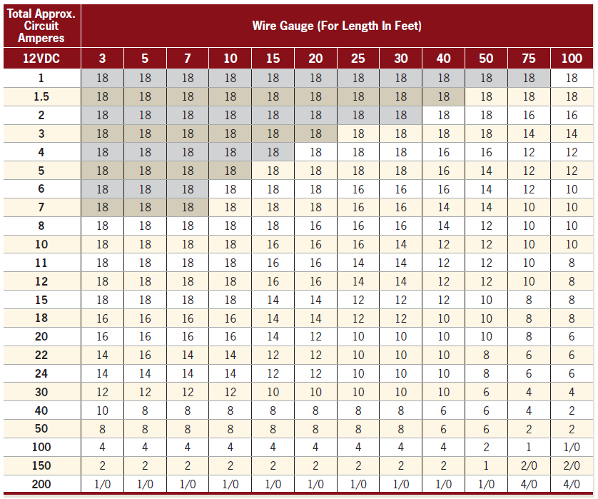
e. Wires & Wire Sizes
At all points in these systems, it is necessary to ensure that you use the correct size wire. Wire heats up when current passes through it. Bigger wire heats less and can handle more current (higher Amps). When too much current passes through a wire, it heats up enough to melt and burn. Of course, you don’t want that. It’s a bad day when your vehicle burns to the ground. Furthermore, longer wires, have more resistance and cannot carry as much current as shorter wires. There are charts to help you decide the right wire size for each part of your circuit. Below is a chart that should be dependable. It comes from this website. Down the left side of the chart is the current or # amps that the circuit will draw. Across the top, is the length of the circuit. Remember that the length of the circuit includes both the positive AND negative wires. So, if your circuit starts at a fuse and uses 9 feet of red positive wire to go to your roof mounted LED light bar and then uses 9 feet of black negative wire to return to your ground connection, that is a total circuit length of 18feet. For a light bar drawing 3.3 amps and 18ft circuit length, you need 18-gauge wire or larger. I rarely use any wire smaller than 16gauge (note that 16-gauge is LARGER than 18 gauge), personally. If your air compressor requires 40amps and the circuit is 10feet long, you need 8-gauge wire. If it falls between sizes, always round up to the next larger size for safety.
Stranded wire is recommended for most automotive use because of its flexibility and resistance to breaking under vibration. Automotive “primary wire” will be suitable for most use. For really large wires, like battery cables, I recommend buying welding cable or wire that is labeled “automotive battery cable” these types of wire will be even more flexible than normal stranded wire in the large sizes. This makes It easier to route through all the twists and bends in automotive applications.
If you are installing an inverter to supply 120Volt AC power (household power), you must ensure that the wire you use on the 120Volt AC portion of the system has an insulation rating of at least 300volts for safety. Most automotive primary wire you buy will only be rated for 60volts and is NOT suitable for 120volt AC circuits. In most cases, for our purposes, this should not be an issue. Most of the inverters we install will have 120V AC outlets built in. You can plug your load directly into these outlets or even use a short extension cord.
V. System Design Samples
Here, I will go into more detail about the six system designs I mentioned in the chart up in section III.
A. Dual vehicle battery setup:
This is as simple as it sounds. Just add a second battery in parallel with your vehicle’s starting battery. This is a relatively inexpensive system. Its major disadvantage is that you can inadvertently discharge both batteries so low that they will no longer start your engine. But, for very infrequent use, just to run a few lights, stereo or charge phone and camera batteries, it can be just fine. You must be able to determine when to start your engine to recharge the batteries. You could add a simple battery monitor to help remind you of this. I will talk about battery monitors in one of the following systems.
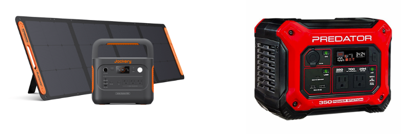
B. Power Bank (Store Bought):
Here, I am talking about Portable power stations that you have most likely seen advertised on the internet and TV. Some examples are Jackery, Bluetti and many others, even sold by Harbor Freight and Temu. These are “All-In-One” solutions that you purchase, and they are ready to be charged and used with little or no assembly required. If you want a system that is easy to transfer from one vehicle to another or even use in the house during a power outage, this is the way to go. You should still take the time to analyze your goals and needs as outlined above. Especially research the quality of what you are buying. Some units are pure junk, and either won’t last very long or could even damage the equipment you plug into them. I recommend staying with the higher quality name brands. Be careful how you use them. During heavy use, they could build up heat. That is a natural part of the process. So, make sure you leave room for cool air to circulate around them. If the unit has vents and built-in cooling fans, make sure all vents are clear and unobstructed.
These power stations have a wide variety of features. Different types of batteries for various performance levels, different types of outlets to plug in devices (12VDC, Various USB ports, 120VAC household power), different ways to recharge them (120VAC, 12VDC, solar panels), inverters to supply 120VAC, sometimes built-in displays for state of charge and battery usage info and even Bluetooth or WiFi connectivity so you can monitor performance on your phone or tablet.
It is possible to build your own portable power station. But it may not be worth the effort, financially, especially if you do not already do a lot of electrical and electronic work and have the tools and basic materials. Remember, it’s more than just the cost of a battery. You would need the battery(s), various sizes of wire, connectors, many of which should be properly crimped or soldered together with heat shrink insulation, an enclosure to hold everything, fuse holders, fuses and circuit breakers, the various DC outlets and USB ports, Inverter and AC outlet, battery monitoring device so you know state of charge, port and cables for re-charging the system, tools and more. The sum of the parts can easily exceed the cost of even a low-end store-bought system for a truly portable setup like these. Something to note is that these power stations are normally rated in Watt-Hours (WH), not Amp-Hours (AH). They do that because the outputs are often a mishmash of different voltages. So, don’t get your numbers mixed up. A 300WH power station being used to power 12volt devices will last 25Amp-Hours. But a 100AH, 12volt marine battery will provide 1200WH. When you compare the ratings in the same units, you see that a battery that size can provide 4 times the power.
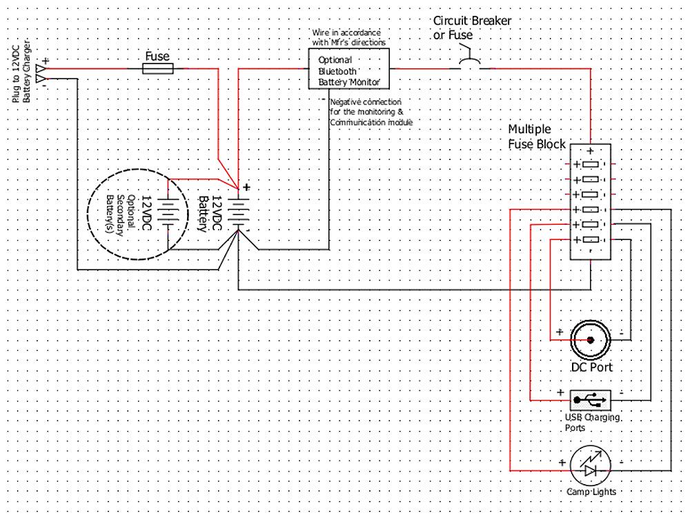
C. Separate Battery Bank System:
Here we start getting into the act of building a custom system. This is not something to be taken lightly. It is not cheap. I began mentioning the components in the section above. Cutting corners can cause equipment damage and injury. But the customization can make it all worthwhile. The ability to separate parts of the system and mount them where they fit in your vehicle can be a huge advantage. That leaves more room to pack your favorite camping or tailgating gear because you have installed the electrical system in otherwise unusable nooks and crannies.
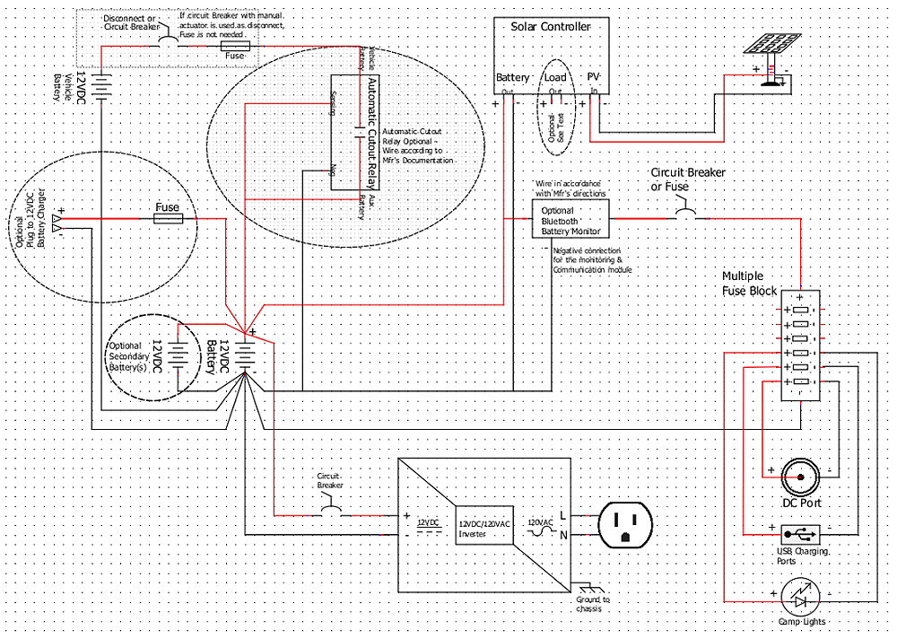
What I mean by a “Separate Battery Bank System” is that it is not tied to the vehicle’s OEM electrical system. Therefore, if you use every available watt-hour of capacity of this system, you can still start your engine and drive home. That is important. Below is a sample of this type of system, showing the basic components you need. I will mark optional items where appropriate. It is important to use fuses and circuit breakers and to use the proper size wire. These are safety factors that will prevent equipment damage, fire and injury. DO NOT cut corners on safety. You will be sorry. In good circuit design, you find the expected load for the circuit “X amps”. Then size your wire and overcurrent protection (fuse or circuit breaker) at 125% of X. That way the fuse protects the load and the wiring from overheating and causing a fire.
In this diagram, I show 2 optional items. One, connecting extra batteries in parallel for greater capacity. And second, a battery monitoring device to help you stay informed about how much power is left in your battery(s) and how fast you are using it. The easiest of these to use are usually equipped with Bluetooth or WiFi. That way, you can communicate to them through your smart phone, tablet or PC using the manufacturer’s app. Be sure to follow the manufacturer’s directions for connecting them properly in your system.
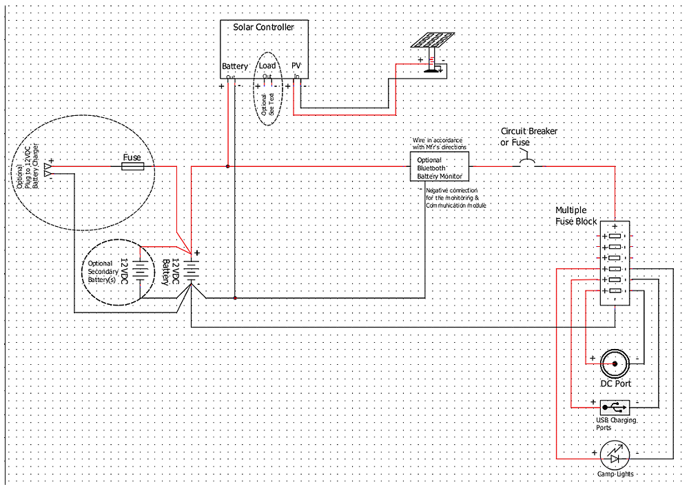
D. Separate Battery System with Solar re-charging:
Expanding on the previous system, we can add solar panels. This gives us 2 advantages. First, we can recharge the storage battery(s) without needing to plug into a battery charger somewhere. Second, It extends the capacity of our batteries because, during sunlight, the solar panel(s) will be supplying power to our loads in addition to the battery bank. Therefore, we will not be depleting our battery charge if the solar panels are putting out enough power from the sun. The output of the solar panels will vary depending on the intensity of the sun. For example, if you have a 100watt solar panel, on an extremely bright, cloudless day, it will supply closer to 100watts of power, if the system needs it. On a cloudy day maybe only 60 watts and on a very cloudy day under heavy shade (camping in the forest) maybe only 20 watts. Keep this in mind when designing your system and choosing solar panels. I once camped several days in the forest in North Carolina in June. The weather turned rainy, and my campsite was heavily shaded so my 200watts of solar panels only produced about 50 or 60 watt-hours over the whole 2 ½ day campout. I ran almost entirely on battery power alone. In the wintertime, when daylight hours are shorter, you will re-charge less simply because there are fewer hours of daylight available. Remember when we talked about Amp-hours and Watt-hours. On a bright sunny day in mid-July, you might be able to put {90watts X 10 hours = 900 Watt-hours } back into your batteries. With the same system on a partly cloudy day in March, you might get {60Watts X 7 hours = 420 Watt-hours} power produced.
Notice the solar controller may have more than one set of output terminals. The battery terminals would normally be connected to the system as I have shown them. These terminals will supply voltage any time the panels are producing enough energy. The “Load” terminals, if your controller has them, will supply voltage to power loads directly, independent of the battery system. The controller app should give you control of this output so you can turn it on and off at will when power is available from the solar panels. I find it preferable to use the solar panels and controller as I have them shown. This allows them to charge my batteries. Then my batteries can supply power to my loads. Study the documentation for your components and use them to your best advantage in accordance with the manufacturer’s instructions.
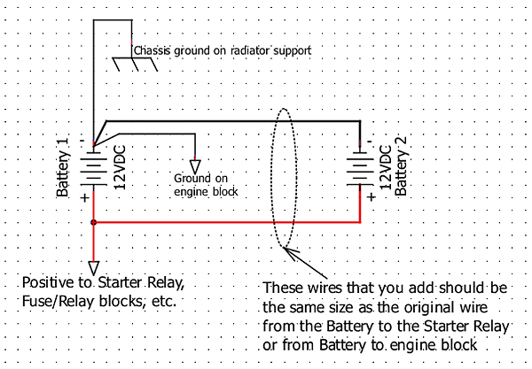
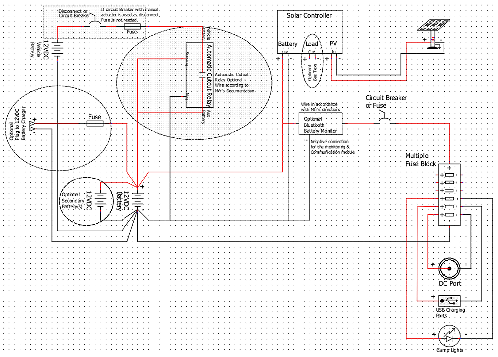
E. Battery Bank With/Without Solar, integrated with Vehicle battery and charging system:
This is where things get more complicated. At first glance, we might think “All I have to do is add 2 big wires from my system to the vehicle battery.” Wrong. In older vehicles, It is almost that simple, as my diagram below will show. In newer vehicles, I would estimate after 2010, the vehicle battery/charging/starting systems began getting more complicated. In U.S. Rangers, this didn’t show up until 2019 when the newest generations were introduced and evolved to match the international market. Now-days, we have vehicle charging systems and battery monitoring systems (BMS) that do not like interference from “outside sources” as in the systems we are discussing. When these vehicles detect voltages and currents they don’t expect, they see the extra battery capacity and charging from “other sources” like solar panels as an electrical virus. The newest Rangers, Explorers and Broncos may have a setting in the customization menu system that will allow you to set a limit on current flow to the auxiliary system. But you should use a DC-DC charge controller to do this properly on the newer vehicles. This controller would replace the ACR in my drawing here. Installing a DC-DC charger between the systems and adjusting the software limit will reduce the current between the systems. This will allow you to use smaller gauge wire and circuit breaker/fuse for this portion of your project.
NOTE: Be sure to check out ‘Adding an Auxiliary Battery to a 2019 and Newer Ford Ranger‘.
Otherwise, yes, it is almost as simple as adding two big wires back to your vehicle battery. But, for safety, let’s add a couple things. First, we will add a disconnecting device. A battery disconnect needs to be installed close to the vehicle battery so we can isolate it and “save it’s life” if something goes wrong with the auxiliary electrical system. Second, we need a big fuse or circuit breaker to do the same thing automatically. This is to protect the vehicle battery in the event that some catastrophe occurs with the auxiliary system and you are incapacitated (injured in an accident or just not close enough to the vehicle to respond rapidly). It adds vital overcurrent protection to prevent fire and equipment damage. If you use a circuit breaker that can be manually operated, this can serve as your disconnecting means. But you must be able to operate it manually. A fuse takes too long to remove.
Optionally, you might want an Automatic Cutout Relay (ACR). This is a device that senses the vehicle battery voltage and compares it to the Auxiliary electrical system voltage and disconnects them from each other when certain conditions exist. I am using one and have it set so in order to isolate the two systems from each other in a way as to automatically prevent me from drawing too much power from the vehicle battery. That way I should always have enough voltage to start the engine, but I can still draw my auxiliary system down to a lower level of charge. The device I used also had provisions for me to add a manual switch to force the systems to be either isolated or combined. I happen to like exact control over my system. It is possible to use this design without the Solar panels and controller. In that case, you would only be able to charge the batteries by running the vehicle engine (alternator) or connecting to a separate battery charger.
As mentioned above, you can replace the ACR with a DC-DC charging controller. This is a “battery charger” that uses your vehicle battery to re-charge your auxiliary battery(s). It is just like using a battery charger plugged into the wall at home, except its source of power is your vehicles battery and charging system instead of 120V AC power from a wall outlet and it is permanently wired into your system. This will limit current flow between the 2 systems, maybe to a max of 25 or 30 amps. Therefore, you can use smaller wire and smaller fuse or circuit breaker for overcurrent protection. I only drew the ACR in this diagram for simplicity.
F. Full System Plus Inverter:
In this last section, we’ll add an inverter to provide AC power. The inverter acts as a load on our Auxiliary electrical system, the same way a refrigerator or camp lights do. However, if you buy a large inverter, say 1200watts, that is a large load (100amps) on our 12volt system. So, the little fuse block we installed for 12volt loads earlier probably isn’t up to the task. We need big wire and a big fuse or circuit breaker. Be sure to use a large fuse or circuit breaker to protect against overcurrent and prevent equipment damage. Again, the ACR shown can be replaced by a DC-DC charging controller.
VI. Conclusion:
Your system can be as simple or as fully featured as your budget and skills will allow. You will be happiest if you sit down and plan it properly as I have outlined. Take your time. Don’t cut corners. Plan a bit of extra capacity for future growth. If you can, wait and save up enough money to build the system using the very best design and components that you can. Or maybe your needs will be best met with a store-bought system that you can charge up at home and take with you for tailgating at this weekend’s ball game.
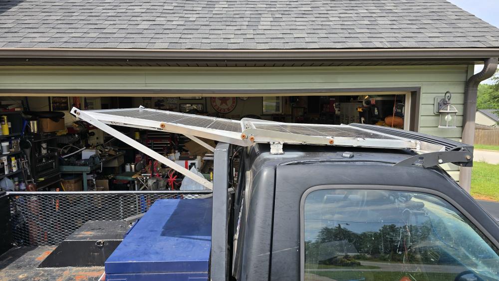
Here are a few photos of the system I built in my 1993 Ranger single cab. It is a full-featured system using two 100watt solar panels, two 100AH group 31 marine batteries, a 200w inverter and integrated with the 64AH vehicle battery/charging system. I’ve been using it a few months now. On a recent trip to Colorado, I even plugged in a friend’s refrigerator and re-charged his power station while charging my own batteries and keeping my refrigerator cold on a partly cloudy day. Maybe these will inspire you. I expect to be building another system soon and will try to produce a video of that process.
The two 100-watt solar panels deployed on the roof.
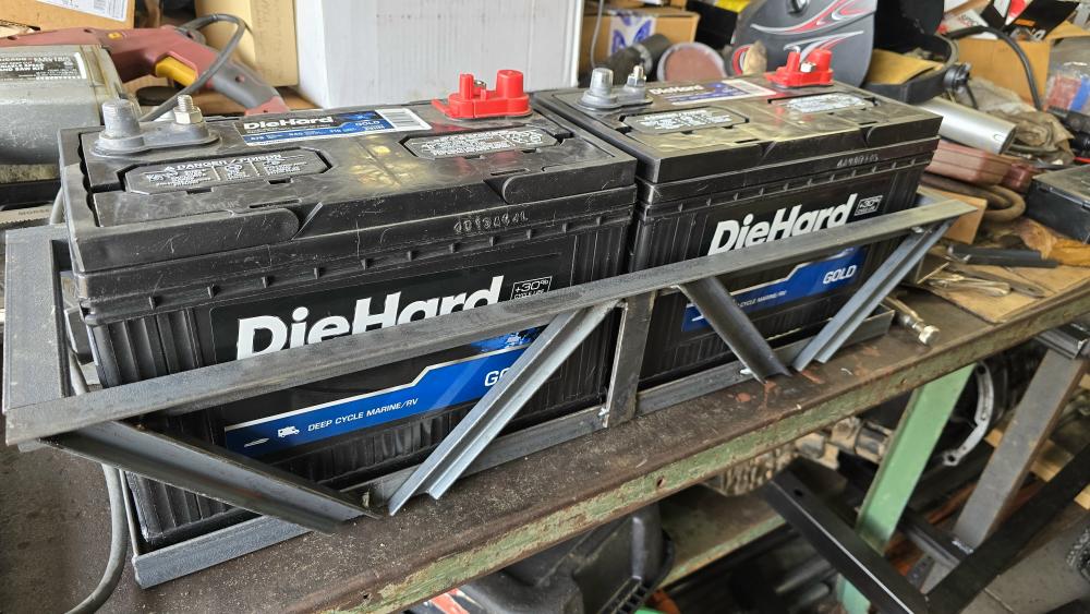
Two 100AH Group 31 marine batteries are in a frame mounted under the bed where the spare tire was formerly located.
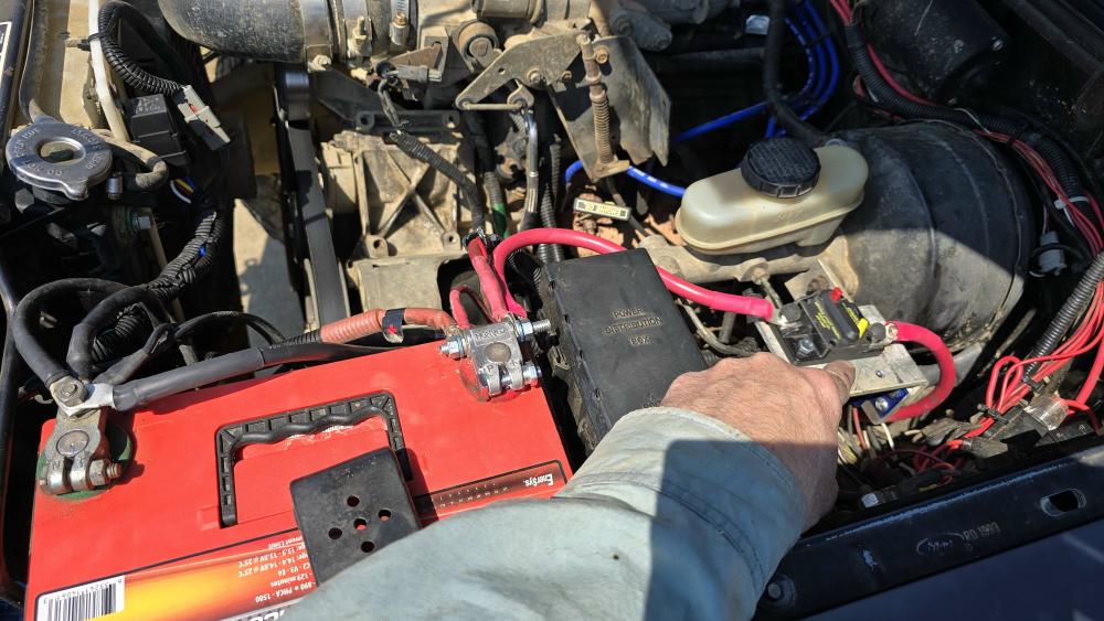
Here, I am pointing to the circuit breaker / battery disconnect in the engine bay that can be used to separate the vehicle system from the auxiliary system.
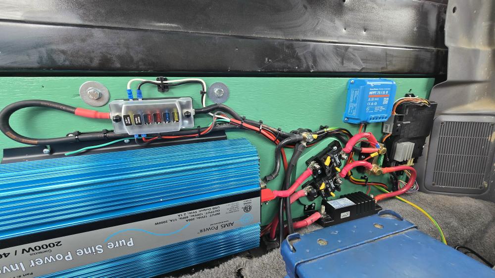
The majority of the system is mounted to the rear cab wall, behind the seats. This view shows the inverter, several circuit breakers, solar controller, battery monitor, ACR, and a small fuse panel for low power loads. The black box at the far end is the electric transfer case controller for the truck. It was already mounted behind the seats.
And finally, I built this waterproof connections box that mounts under the bed on the passenger side of the truck.
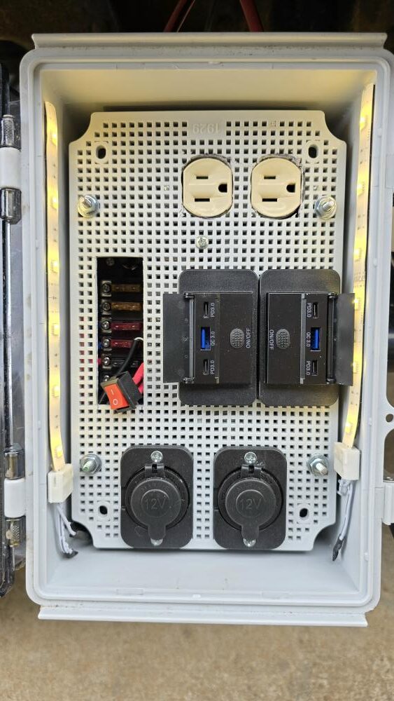
It houses two multi-port USB charging stations, two 12VDC power ports, a 120volt AC outlet and has lights for night use.
About The Author

Occupationally, my heart has always been in industrial maintenance. I am currently an Equipment Services Associate at BMW Manufacturing Co. In Greer, SC. My career, beginning in 1982 has spanned from Nuclear qualified electrician in the U.S. Navy (USS Dace, SSN 607) through industrial maintenance with Michelin Tire Manufacturing, International Paper (corrugated box plant), owning my own electrical contracting company, (I am a Licensed Master Electrician) and commercial building maintenance with BlueCross BlueShield of SC where I served several roles including assistant IT Facilities Engineer and Building Maintenance Supervisor. My area of expertise has always focused on electrical things. But my knowledge and experience are strong in many other related fields.
Growing up, I was in Boy Scouts, achieving rank of Eagle Scout. Also, a member of Order Of The Arrow. I have been camping since I was a baby with family, then Boy Scouts and on my own. Offroading and working on my own vehicles started many years ago. I am a Born-Again Christian and my faith in Christ is an integral part of who I am. I will not force those beliefs on anyone. But all are welcome to contact me privately for more info in this area.