
Introduction
Starting in 1995, the 3.0L received a distributorless ignition system (DIS). This system uses a set of positioning sensors, one on the engines crankshaft and one on the engines camshaft, to determine when to fire the spark plugs. since the oil pump is driven by the camshaft via the distributor on this (and many “V” pushrod engines), Ford could not completely do away with the distributor. The bottom half that engages the camshaft and drives the oil pump would have to remain (less Ford redesign the entire block). Since the bottom half of the distributor would have to remain anyway, the easiest way to retrieve a camshaft position signal would be to mount a sensor right on top of this “cam syncro shaft” (or Camshaft Synchronizer).
The cam syncro shaft has a small metal flag on the top of it. The camshaft position sensor bolts to the top of the cam syncro shaft, and this metal flag passes through the sensor…in this way the engine knows exactly where the cam is in its rotation (and thus, when the #1 cylinder is on its compression stroke).
(NOTE: Also referred to as the CMP CaMshaft Position sensor. Do not get this confused with a CPS which is a Crankshaft Position Sensor)
Here’s Where We Get Into Trouble
The cam syncro shaft rides on a set of bushings. For some reason (and this doesn’t appear to be a problem on distributor engines for some reason), these bushings seem to wear prematurely, thus allowing the cam syncro shaft to wobble. At this point, the cam syncro shaft will usually emit a noise very similar to a belt squeal (but not always). If left unchecked, the bushings will continue to wear to the point where the metal flag that is supposed to pass through the cam position sensor contacts the sensor. This puts a sudden halt on the cam syncro shaft. The gear that engages the camshaft itself is attached to the cam syncro shaft with a roll pin. The force of the cam syncro being stopped and the cam still spinning either rips the teeth off the gear or sheers the roll pin…either case causes the cam syncro shaft to disengage the cam. With the syncro shaft no longer turning, the oil pump is no longer turning, thus oil pressure drops to zero.
It can take a matter of seconds to completely destroy an engine while driving at highway speeds and no oil pressure. Even if you see the oil light come on, you might not be able to safely pull over and shut the truck down in time to save the engine.
If buying a DIS 3.0 with more than 80K miles on it you should replace the syncro shaft. After that, pull the syncro and check it at 50K miles and replace again every 100K miles. Don’t ignore squeaks or long engine cranking times, as these can be indicative of cam sensor or cam syncro problems. If your oil light comes on while driving, as soon as its safe to do so, put the truck in neutral, turn the ignition off, and coast to a stop. These trucks (that being Rangers in general, not just the 3.0) are known for having flaky oil pressure sending units that like to give false low readings. Your next step in this situation would be to verify either low oil pressure or a bad sending unit and take appropriate action.
CMP Sensor
The Camshaft Position (CMP) sensor consists of a permanent magnet, yoke and coil. The CMP sensor is positioned next to the cam gear. As each cam gear tooth passes the sensor magnetic pick-up an AC voltage pulse is induced in the coil. The PCM counts the number of pulses to determine the camshaft speed. The number of pulses counted in one second is the signal frequency.
The Powertrain Control Module (PCM) uses the camshaft position sensor to manage sequential fuel injection and as part of misfire diagnosis. The PCM constantly monitors the number of pulses on the signal circuit. The PCM compares the number of camshaft sensor reference pulses and the number of crankshaft position sensor reference pulses received. If the PCM receives an incorrect number of pulses, Diagnostic Trouble Codes (DTCs) should be stored in the PCM. Some PCM systems will then default to multi-port or “gang-fire” injector operation. The camshaft position sensor signal is required to sequence the injector operation to the proper cylinder timing. If the camshaft position sensor or circuit is faulty, most engines will start. However, the PCM misfire diagnostic will likely be affected.
On the 1991–94 2.9L and 3.0L engine, the distributor stator is the Camshaft Position (CMP) sensor, and it is a Hall effect magnetic switch. On the 1995+ 3.0L engine, the CMP is mounted on the oil pump drive assembly, located towards the rear of the block. it is also a single hall effect magnetic switch and it is activated by a single vane, and is driven by the camshaft.
Oil pump drive mounted Camshaft Position Sensor
Symptoms
There is usually (but not always) a squealing sound coming from the engine. Generally from the rear of the engine. It may also be that your engine just quit and displayed no oil pressure.
What To Replace
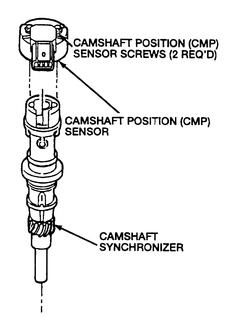
You need to replace the whole unit (Camshaft Synchronizer & Camshaft Position Sensor). The camshaft synchronizer shaft has a gear that engages the camshaft. It’s much like a distributor but has a position sensor mounted to it at the top. The shaft wears out and starts squeaking.
CaMshaft Position Sensor – Step Style or Non-Step Style
Non-Step Style – If you look inside the connector on the Camshaft Position Sensor; you are looking at the socket (female) side of a quick connect plug. For the non-step style plug socket, the hole is the same size in the front of the plug socket as it is at the back (bottomed out in the socket hole) end of the plug socket. This means the tip of the plug (male end of the quick connect) from the vehicle will be the same size as the back end of the quick connect plug, (no step down in size.)
Step Style – If you look inside the connector on the Camshaft Position Sensor; you are looking at the socket (female) side of a quick connect plug. For the step style plug socket, the hole is large at the front of the socket, then about .25 (1/4) inches into the socket, the size of the socket steps down about .0625 (1/16) inches. This means that .25 (1/4) inches into the socket, the socket hole steps down and is smaller than the socket hole at the front of the socket. The smaller socket dimension remains this size the rest of the way back (bottomed out in the socket hole) of the plug socket. Looking at the vehicle side of the quick connect plug, the tip of the plug (steps down in size.)
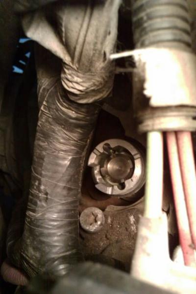
Location (1995+ Ford 3.0L)
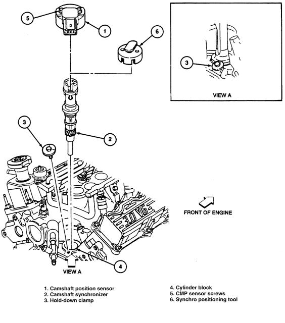
The the Camshaft Syncro Shaft (Camshaft Synchronizer) is on the top back passenger side of the engine. There is a hold down bolt (#3 in diagram below) that holds it in place. The Camshaft Position Sensor is attached to the top of the Camshaft Sycro Shaft.
How The Repair Manual Says To Remove & Install It
Removal & Installation (1995+ 3.0L)
NOTE: If the camshaft position sensor housing does not contain a plastic locator cover tool, a special service tool such as T89P-12200-A, or equivalent, must be obtained prior to installation. Failure to follow this procedure may result in improper stator alignment. This will result in the fuel system being out of time with the engine, possibly causing engine damage.
- Disconnect the negative battery cable.
- Remove the ignition coil, radio capacitor and ignition coil bracket.
- Disengage the wiring harness connector from the CMP sensor. NOTE: Prior to removing the camshaft position sensor, set the No. 1 cylinder to 10°After Top Dead Center (ATDC) of the compression stroke. Note the position of the sensor electrical connection. When installing the sensor, the connection must be in the exact same position.
- Position the No. 1 cylinder at 10°ATDC, then matchmark the CMP sensor terminal connector position with the engine assembly.
- Remove the camshaft position sensor retaining screws and sensor.
- Remove the retaining bolt and hold-down clamp.NOTE: The oil pump intermediate shaft should be removed with the camshaft sensor housing.
- Remove the CMP sensor housing.
To install
- If the plastic locator cover is not attached to the replacement camshaft position sensor, attach a synchro positioning tool, such as Ford Tool T89P-12200-A or equivalent. To do so, perform the following:
- Engage the sensor housing vane into the radial slot of the tool.
- Rotate the tool on the camshaft sensor housing until the tool boss engages the notch in the sensor housing.NOTE: The cover tool should be square and in contact with the entire top surface of the camshaft position sensor housing.
Fig. 2: Attach the Camshaft Position Sensor synchro positioning tool to the housing

Fig. 3: Camshaft Position Sensor positioning for the 3.0L
- Transfer the oil pump intermediate shaft from the old camshaft position sensor housing to the replacement sensor housing.
- Install the camshaft sensor housing so that the drive gear engagement occurs when the arrow on the locator tool is pointed approximately 30°counterclockwise (the sensor terminal connector should be aligned with its matchmarks) from the face of the cylinder block.
- Install the hold-down clamp and bolt, then tighten the bolt to 15–22 ft. lbs. (20–30 Nm).
- Remove the synchro positioning tool.
- CAUTION: If the sensor connector is positioned correctly, DO NOT reposition the connector by rotating the sensor housing. This will result in the fuel system being out of time with the engine. This could possibly cause engine damage. Remove the sensor housing and repeat the installation procedure beginning with step one.
- Install the sensor and retaining screws, tighten the screws to 22–31 inch lbs. (2–4 Nm).
- Attach the engine control sensor wiring connector to the sensor.
- Install the ignition coil bracket, radio ignition capacitor and ignition coil.
- Connect the negative battery cable.
How Our Forum Members Say To Remove & Install It (1995+ 3.0L)
By Forum Member mercuryseven (HERE):
A nasty little device. I was throwing a P0340 (CaMshaft Position sensor fault) and the truck was barely drivable; this is a 2002 Ranger Edge with a 3.0. I parked it and ordered up a Motorcraft synchro, got home at eight and finished about nine.
For those unaware, this is notorious for failing in the Ranger (Post ’95) and the best case scenario when it does is cause performance issues, the worst case is it destroys your engine. The shaft running down this is what drives your oil pump and it’s being handled by a gear spot welded to it. In my case, the shaft had about 3/4″ of play and the gear was severely worn to an almost razor like edge because of the float in the main shaft. This is what does it. As the bushings wear, the softer metal gear is allowed to float against the harder cam, wearing the rectangular gear teeth into more of a sharpened oval shape. This dumps a bunch of metal in your engine and starts a snowball effect. Had this gear failed, the engine would have likely quit but not before it was starved of oil and seized.
If you’re over 70K in your truck, change it, it takes longer to clean up than the project does. I got a Motorcraft CMP for $165 but they will give me $50 for the core. You can pick up a reman CMP for about $100 out the door or $50 with a core. There are two types, “With Step Up” and “Without Step Up”. This refers to the connector type. All EDGE 3.0’s are “Without…”. You can either pull your sensor before picking up a new one or just buy the “Without”…they work on everything.
Pull the negative.
The CMP is at the rear of the block, on top.
Two 7/16 bolts hold the sensor to the synchro, remove these before disconnecting the harness. Pull the sensor off and remove harness – it’s a tab release.
Mark the position of the shaft vane onto the manifold with a grease pencil or marker. The alignment tool and the TDC method is pointless, these teeth take a big bite, you’re either off terribly or right on. Mark the body position.
The hold down bolt is behind and slightly to the passengers side of the shaft centerline. It’s a 1/2” socket on a slight angle back.
Remove old one. Curse it and point while saying things like, “Look how bad this is”. Then drop nothing in that hole.
Cover the new one in oil, from o-ring down. Lucas additive.
Drop in CMP. It will self align with oil pump shaft. It’s a spiral type gear and the pitch dictates a one tooth clockwise jump. Aim for one back – for six o’clock shoot for five.
Your shaft vane now in place, align CMP body to mark.
Once it’s aligned and fully seated against the block, insert the 1/2″ hold down bolts.
Connector sensor to wiring harness and reseat onto CMP, tighten two 7/16″ bolts.
Reconnect negative.
When you start it, just let it idle. Don’t do anything punchy until that CMP can saturate itself with oil. Ford dealer man says to let it go for about a minute like that while the computer makes tiny adjustments to the now consistent firing timing.
Result was a cleared P0340 code and a completely different engine.
The bonus to all of this is that in the process of tracking down this problem, I replaced the ICV, the MAF sensor, the plugs, plug wires, coil, fuel filter, throttle body, cleaned air box…and now, finally, I own a code reader.
By Forum Member fourwheelford:
Disconnect the battery ground cable before doing the work.
If you take the sensor off there is a little key that sits on top of the shaft. It spins and contacts the sensor. The opening (slot) where that takes place is where the key should be at TDC(Top Dead Center) on the compression stroke. If its on the exhaust stroke, the key will be to the opposite side of the slot. Use some whiteout and mark the placement before you remove the sensor so you can put it back on right. Put the motor at TDC. There is a small hold down bolt (10mm I think). Remove it and the sensor should wiggle right out. Replace it in reverse and make sure that the key stays in the center of the slot. Tighten the hold down bolt and put the sensor back and plug it in. The critical part is putting everything back the exact way it came off. It’s a pretty easy job though. I did mine as preventative maintenance about 2000 miles ago.
When I did it I used the harmonic balancer and left the spark plug in it. I cranked the motor by hand until I could feel the compression build up. Once I could feel the compression build up I set it to the zero mark (five teeth back from the TDC letters) on the balancer, NOT the actual TDC letters. When I removed the sensor the tooth was right in the middle of the slot.
I lubed up the new syncroshaft and indexed the gear so it would go in into the same spot. I put everything back together and she fired right up with no CEL (Check Engine Light). The tool is really not needed. If you mark the 0 degree mark on the balancer with white out, and line it up with the CRANK positioning sensor (black sensor next to the balancer) on the compression stroke, then you will be at TDC. Install the syncro with the key in the center of the slot and with your line that you marked on the block or wherever and see how she does. Make note of where the key is before you pull it out. It will give you an idea of how far off you were.
Connect the negative battery cable.
By Forum Member Runnin’OnEmpty:
Disconnect the battery ground cable before doing the work.
If you look closely there’s a mark on the crankshaft damper that’s at 0* TDC. You may have to sandpaper the damper to see it, but it’s there. It coincides with the fifth ‘tooth’ on the tone ring after the gap. To check for the compression stroke, just remove the cam sensor and see if the key and gap are close to being aligned. If so, then the engine’s on the compression stroke. If they’re almost 180* apart, then turn the engine over (1) revolution to get on the compression stroke. Remember the synchro ‘key’ and ‘gap’ won’t be aligned perfectly, they’ll just be close; (The key will be about 14* ccw from the gap, if I recall correctly).
Connect the negative battery cable.
From Forum Member fireant:
I just did a replacement of my Cam Position Sensor and Synch Shaft. Most autoparts places have it listed as a Crank Angle Sensor… go figure.
Anyways, for future reference here’s a brief how-to for a 95 3.0L:
- Disconnect battery. Get a stool and access the motor from the passengers side near the firewall.
- Unplug the 6 spark plug wires from the harness on the top of the engine.
- Use a 12mm socket to remove the spark plug wire harness from the top of the engine and move it all aside so you can reach between the engine and firewall. Unplugging the harness will help some.
- Use a stubby flathead to pry loose the plug from the sensor
- If its stock, use a 6mm socket or driver to loosen the top two screws and carefully remove the sensor.
- Use a camera phone to take a picture of the shaft’s position as it is before moving or prying. You need to get a record of the exact position of the half-circle part that’s on the top. Mine was mangled, but I took a pic anyway.
- Using an extension or two and a 10mm socket, remove the bolt/washer that is holding the assembly down in postion. This is hard to see, as its between the bottom of the assembly and the firewall, down next to where it enters. Grope around down there and you’ll feel it… you might need to pull some of the wires out of the way to get to it.
- With that gone, you can now lift out the whole assembly… be sure to pay attention to the position of that half-ring (mark it with a sharpie, maybe). When you put the new one in, the half-ring needs to be exactly back in that spot. If yours is mangled like mine was, look very carefully at the base the ring sits on for where it USED to be, and use this as a reference. I also recommend NOT leaving it for a core charge until you are done, so you have it as a reference. Also, DONT crank or turn the motor in any way while this is out, or you’ll have to do a bunch of timing settings.
- Getting the new one in takes some lubing and jiggling, and a little tapping with a rubber mallet and dowel, but it will go in. When the teeth engage, they will turn the half-ring a few degrees bit clockwise, so you’ll need to compensate for that before inserting. Be firm but not excessive
- Replace the bolt. Replace the sensor and plug it in. Replace the spark plug harness and plug it all back in. Reconnect the battery.
From Forum Member atlsud:
Take a photo before taking the synchro out. The trigger does rotate counterclockwise as it comes out. I set the trigger in the similar position on the new synchro. As I place it in, the gears engage and turn the trigger clockwise. It took me a few times re-setting the trigger and seating the synchro to get it right.
Here is a pic I took before I took it out.
Note From Wicked_Sludge:
Just make sure the little flag on the end of the syncro, and the body of the syncro itself are both in the same orientation during installation as they were during removal. There’s really no reason to set the engine to TDC before removal (unless your using fords special tool for setting CMP timing).
Diagnostic Trouble Codes:
Incorrectly installed gear driven camshaft position (cmp) sensor synchronizer assemblies causing surge, loss of power, malfunction indicator lamp on and diagnostic trouble codes P1336, P1309 and P0340.
Reference Video
Reference Photos

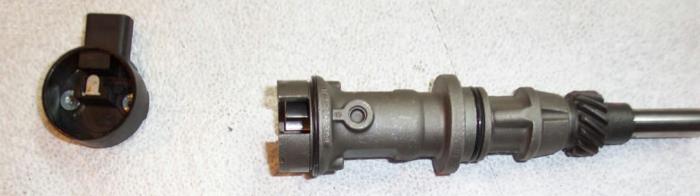
(3.0L Camshaft Sensor & Synchro – top new – bottom old)
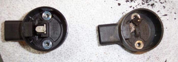
(3.0L Camshaft Sensor – left new – Right old)

(3.0L Camshaft Synchro – left old – right new)
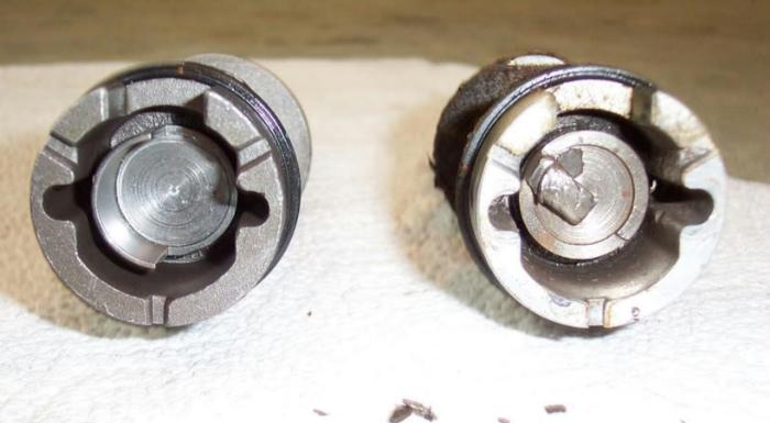
(3.0L Camshaft Synchro – left new – right old)
Contributors
This information was put together by TRS forum member ‘Wicked_Sludge’ and submitted to the author to be published at The Ranger Station to help other Ford Ranger owners.
Links
Be sure to check out our Ford Ranger 3.0 Forum
Related Articles
1991-2009 Ford Ranger 3.0L V-6
60mm 3.0L Escape Throttle Body on 3.0L Ranger Intake
1999 Ford Ranger V6 3.0L FFV Head Gasket Replacement
Ford Camshaft Position Sensor (CMP) / 3.0L, 4.0L & 5.0L
Last Updated:
About The Author
Jim Oaks is the founder of TheRangerStation.com, the longest-running Ford Ranger resource online since 1999. With over 25 years of hands-on experience building and modifying Ford Rangers — including magazine-featured builds like Project Transformer — Jim has become one of the most trusted authorities in the Ford Ranger off-road and enthusiast space.
Since launching TheRangerStation.com, Jim has documented thousands of real-world Ranger builds, technical repairs, drivetrain swaps, suspension modifications, and off-road adventures contributed by owners worldwide. TheRangerStation.com has been referenced in print, video and online by enthusiasts, mechanics, and off-road builders looking for practical, and experience-based information.