
How it’s supposed to work (and why it often doesn’t work like so)
Steering continues to be one of the most overlooked, often misunderstood pitfalls on these suspensions, so I felt this subject deserves it’s very own page.
As many owners of lifted ‘Twin-Traction-Beam’ (or 2WD ‘Twin-I-Beam’) trucks probably already know, keeping them from chewing up that brand new set of expensive tires (as well as keeping it pointed straight down the road) can be difficult sometimes. Blame usually gets put on the camber curve that’s characteristic to this suspension, and the resulting assumption is that nothing can be done about it (in some cases even driving people to swap solid (monobeam) axles into it’s place).
Problem is… the camber curve bears relatively little of the blame for the rapid tire wear and poor handling.
Attention needs to be turned away from camber, and toward the steering linkage that connects the front wheels with the steering box on the frame, as this is where most of these issues stem from.
Here’s why:
Lifting the vehicle moves the axle further away from the steering box on the frame (by the amount the lift is tall). This results in the steering linkage being pulled up at a steep angle from horizontal, which then allows drastic changes in the front wheel toe alignment to occur with suspension movement (a form of bumpsteer– this is something completely independent from the camber). The front wheels are steered toward (or away) from each other as the suspension moves, which basically results in the tires getting dragged sideways across the pavement.
(a description of toe, along with caster and camber can be found on this page)
So you’re likely thinking: “Well that’s what a Dropped Pitman Arm is for, so you bring the steering linkage back down to where it was”. Great. But here lies another problem: Few (if any) of the pitman arms that are currently provided by the suspension industry have enough drop to fully correct for the lift’s height, most only come down about 2″ compared to the stock arm. This still leaves a high amount of angle on the steering linkage, and is why these problems persist even after installing such arms (The results can be especially disastrous when softer coils are used for increased articulation).
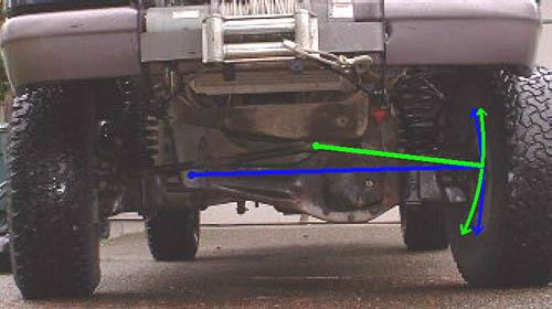
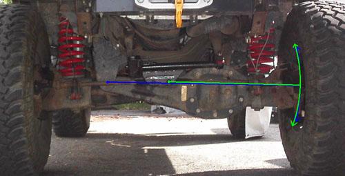
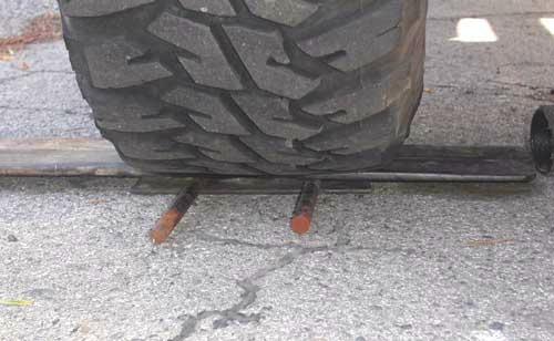
When viewed from the front, the linkage should be at rest directly in front of the TTB axle beam pivots (see photo at top of page).
In most cases this means the entire linkage will be sitting down flat (horizontal) when the truck is parked on level ground, although if you have beams that are modified for lift (sometimes referred to as “cut & turned” or “bent” beams), then each tierod should be positioned in front of each beam (parallel with a straight line that runs from the beam pivot bolt, to where the tierod attaches at the steering knuckle). This applies on both the stock “Y”-style linkage, as well as with aftermarket or custom steering setups.
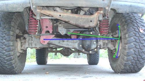
Here’s a graphical representation of what happens when the steering linkage is not in alignment with the suspension beams (Ranger with 4″ suspension lift and typical dropped pitman arm):
As you can see, the arc that the axlebeam travels through (blue), and that of the steering link (green) are not in phase with each other, the two curves run diagonally across at the suspension’s static ride height (separating significantly as the suspension extends downward). As a result, the tires steer away from each other as the suspension compresses (or when the vehicle is loaded), and toward each other when the suspension extends (such as while accelerating, or if weight from a trailer is placed on the rear).
It shouldn’t be difficult to see how this would cause a rapid increase in tire wear, and the effects it would have on handling.
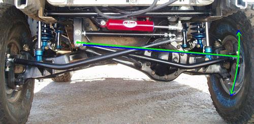
Some of you may have even gone as far as installing something like the Superrunner steering linkage (“K”-style linkage) that Superlift sells. It’s unfortunate this kit also has a similar design flaw in that the centerlink isn’t mounted low enough, and as a result (in spite of claims to help with this issue), it still doesn’t do a whole lot to correct the bumpsteer as evidenced here on a similar 4″ lift (it’s said this kit can be used with 6″ lifts even):
Why these issues have persisted like this for so long is something I haven’t figured out… but no doubt it certainly has created countless headaches and frustration over the years for those who own lift kits with this flaw, which is likely what’s contributed to the common notion that such problems with these suspensions are just “normal”. Ugh.
So what can be done about it?
Skyjacker Suspension offers two different pitman arms with different drop amounts (the only company at the time of this writing that I know of to do so).
Their part # FA400 standard drop arm is the typical example of what’s marketed for a 4-6 inch lift (and is the one they include with the 4″ and 6″ kits they sell). It’s ACTUAL amount of drop is closer to 2″ when compared to a stock arm.
However they also have their part # FA600 “extreme” drop arm which they market as being for 6-8 inch lifts. It drops down an additional 2″ over the standard arm for a total drop of 4″.
These photos show a stock arm (4WD), a typical drop arm, and the Skyjacker #FA600 arm:
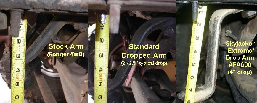
Simply installing the longer arm should reduce or alleviate the issue by bringing the steering’s geometry with the axle closer to what it was stock. It should also be noted the longer arm will quicken the steering ratio somewhat (lowering the number of turns from lock-to-lock).
In this example of a stock linkage with less angle, you can see a definite improvement in the relationship of the two curves, making for less toe change with suspension movement. If this linkage were down another inch or so (or an inch less suspension lift), the parallel area of the two curves would ideally be dead-centered right at ride height, almost eliminating the bumpsteer at all but the extremes of suspension movement:
Here is a Superlift Superrunner linkage where the centerlink has been modified to position the tierods more appropriately with the beam pivots, and again you can see the marked improvement in the travel paths between the beam and the tierod:
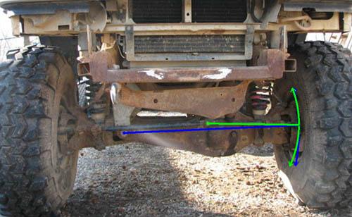
In this picture is a full-custom steering setup (sometimes known as a Crossover or Swingset style linkage), which generally provides the utmost level of control with its long tierods that closely match the full length of the axle beam:
As you can see, the travel paths for the axle beam and tierod deviate very little, resulting in almost no bumpsteer throughout it’s range of movement.
This type of setup is very popular with desert racers where suspensions are regularly put to their travel extremes. They tend to be the most complex however, and the large bends often needed for everything to clear properly on a 4WD axle (mainly due to the presence of the differential housing) can reduce their strength to some extent.
If a rather small amount of bumpsteer can be tolerated at the travel extremes (truck won’t be jumped often), a K-style setup (2nd pic above) I feel offers a good compromise for strength and simplicity on a rig typically used for say, crawling through rugged boulder-strewn trails. It’s centerlink setup puts less leverage on the steering box sector shaft than what you’d have with the longer pitman arm, and the straight tierods are much more rigid than ones having bends in them (which also includes the factory Y-linkage).
Alignment:
So now that you’re familiar with what effects the steering linkage geometry has on handling, let’s look at the aspects of what’s needed for the frontend alignment.
TTB alignment seems to be becoming a lost art in this day & age of modern control arm suspensions (not that it was well-understood during the ’80s & ’90s while they were still in production). Often it seems alignment shops won’t be completely familiar with all of what’s needed (forget about troubleshooting issues (such as with ride height) that could prevent a proper alignment from taking place at all). Other times you run into laziness where the tech doesn’t bother to change an incorrect camber/caster bushing where needed to dial it in correctly, perhaps setting the camber and/or toe only, without paying attention to where the caster ends up. In any case, the end result is a poor alignment that pulls to one side, or worse, ruins your tires in the process (again doing nothing to help the suspension’s image problem).
Alignment bushings:

The caster/camber bushings are located around the upper balljoints on each side. These bushings are available in many different offset amounts, and are insertable in different positions to allow a very wide range of adjustments.
A single bushing is used for setting both parameters, so adjusting one affects the other. You have to find both the correct degree bushing needed, AND what it’s orientation in the axle beam needs to be in order to have the proper amounts of both caster and camber (This is probably a frequent spot where much of the confusion about these things comes from).
There are two types of bushings available: fixed-degree, and fully-adjustable.
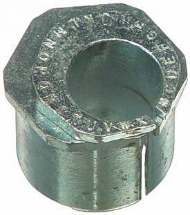
Fixed-degree ones are available in various fixed offset amounts from 0° to approx. 3-½°, and is the type that was used at the factory during assembly:
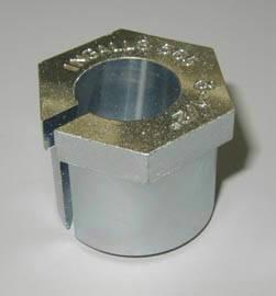
Fully-adjustable ones are just what the term implies, they can be adjusted to any degree amount (this is in addition to being insertable in multiple positions into the axle beam). Such bushings have two-piece construction and are usually indexed with the letters A-Z around the top:
I strongly prefer the fully-adjustable type, as you don’t have to swap the bushings out for different ones any time a different degree is needed, you only need to rotate the two pieces within each other, and then reinsert the bushing back into the beam. The indexing charts they come with (or can be downloaded from the mfgr’s website) are extremely helpful when it comes to making a change of say, 1° to the caster, without incurring a resulting change in camber, you only need to follow the column on the chart from the current camber setting to find the new caster setting, and then reindex the bushing accordingly.
Some examples of fully-adjustable bushings for the D35 axle include: Ingalls #594, Moog #K8986, Specialty Products #24180, and Spicer # 6122025.
These bushings are extremely helpful if doing your own alignment at home where some trial & error might be needed to get it fully dialed in correctly (no need to keep a big box full of different bushings laying around).
DIY
Following is a detailed alignment procedure for performing an ‘at-home’ TTB alignment:
Wheel alignment must be measured with the FULL weight of the vehicle on it’s tires. Because the suspension beams act as levers, you cannot support them anyplace else except directly under the tire’s contact patch, otherwise it will effect a change in the suspension’s height, causing an improper alignment after the vehicle is put back down on it’s tires.
It is also imperative that there is no bind or tension between the front tires on the ground (such as what occurs right after it’s been let off of a jack), this can affect the height of the suspension as well.
(I like to place steel plates with round metal dowels between them under one front tire, and a piece of wood of similar overall thickness under the opposite tire (to keep things level). The rolling dowels will release any bind between the wheels, allowing the suspension to fully settle).
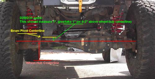
First step is to verify that the suspension’s ride height sits within acceptable limits.
On Dana 28 and Dana 35 axles, this is where the centerline of the axle beam pivot bolts is exactly 1″ higher than the centerline of the wheel hubs on flat ground, give/take 1″.
On Dana 44 axles, the pivot bolt centerline should be the SAME height as that of the wheel hubs, give/take 1″.
If the suspension’s height is not within these limits, there is a good chance that the camber and/or caster cannot be brought into spec by adjustment of the alignment bushings alone, and will need to be corrected (Commonly if the suspension is sitting too low, a spacer or washers placed under the lower spring seats can be used to raise it up. If it’s off by a very large amount (2″ or more), a swap to longer coil springs may be needed).
Camber:
If the suspension’s ride height checks out OK, the next step is setting of the camber (also rough in the toe too if it’s grossly out of spec).
I usually start with the bushings initially set for zero offset (usually “A” or sometimes “M”, depending on the bushing). Some bushings only have a 0.5° minimum offset rather than 0°, in these cases I’ll throw the .5° offset rearward toward the caster so the initial amount of camber correction remains at 0°.
There are a few methods available for assessing the camber, although one accurate way would be by checking it using an inexpensive caster/camber gauge that measures off the face of the wheel rim (an angle finder gauge can be used here as well).
With a chart in hand (so you don’t alter your initial caster setting) adjust the bushing so that the proper camber will be obtained (I like to shoot for about 0.25-0.5° positive camber (tires leaning ever so slightly outward at the top). This allows for when weight of vehicle occupants/cargo is added).
Toe alignment:
You want the tires to be dead-parallel with each other to no more than 1/8″ or so toe in (be sure your tires run true if you’re using a tape measure to check it off the tire treads, a 1/4″ or more wobble in tires is not uncommon, especially with bias-ply tires).
I like to jack the tire up and using chalk or a grease pencil, draw a line along the circumference of the tread by rotating the tire. This will give you a good reference point to measure from without any wobble in the tire affecting it.
With weight on the suspension, measure the distance from your reference point on the tires ahead of the axle, and then again from behind. Adjust the steering linkage so they are the same, to 1/8″ closer together ahead of the axle.
Centering of the steering wheel is done by adjusting one tierod shorter, while adjusting the other side longer by the same number of turns (a drive around the block will be needed to accurately verify steering wheel position). It is not possible to reposition the wheel on the steering column.
Fine-tuning the Caster:
Caster angle is what directly influences the steering’s return-to-center.
If you find the vehicle pulling slightly to one side while driving, adding (or subtracting) a bit of caster on one side will help the wheel return back to straight-ahead when you let go of it (this is where the fully-adjustable bushings mentioned above will come in real handy).
If the vehicle pulls toward the right a little, add between 0.5-1° caster to the passengerside (alternately, you can subtract 0.5-1° on the driverside).
If it pulls left, then the opposite applies; you add 0.5-1° caster to the driverside (alternately, you can subtract 0.5-1° on the passenger side).
If you find the steering has little return-to-center at all (and wanders), it’s possible you may need to add more caster to BOTH sides. In extreme cases, dropping the radius arm mounts down could be required, although this generally shouldn’t be the case if the suspension’s ride height is correct.
The actual caster angle itself on both sides should be set to somewhere between 2-7° (4-5° being ideal).
Conclusion:
Poor handling and excessive tire wear simply don’t have to be tolerated on a lifted Twin-Beam Ford suspension. While it is true these suspensions are very finicky about proper steering geometry, as shown above the issues are very much correctable (in some cases it’s as simple as swapping to a more appropriate pitman arm). Hopefully this information can prove useful in tracking down the issue on your own vehicle. 🙂 ~TRS