
Original Poster(s): Cammeddrz and RICO9
Difficulty: 8.5 out of 10
Time to install: A Weekend
Disclaimer:
The Ranger Station.com, The Ranger Station.com Staff, nor the original poster are responsible for you doing this modification to your vehicle. By doing this modification and following this how-to you, the installer, take full responsibility if anything is damaged or messed up. If you have questions, feel free to PM the original poster or ask in the appropriate section of The Ranger Station.com forums.
Brief Explanation:
This is a great way to covert your already Durasparked 2.8 to Fuel Injection.
Tools Needed:
- Basic hand tools
- Flaring tool
- Wire Crimper
- Grinder
- Drill
- Various wire connectors
Why?
Lets start with addressing why you would want to do this as opposed to other TBI writeups on other sites:
1. The ford 3.8 injection will not work with a Duraspark distributor
2. The ford 3.8 injection pours too much fuel for a 2.8 which is 35% smaller displacement than the injection is designed for
3. The ford 3.8 injection requires you to jury-rig the IAC (idle air control valve) because there is no provision for it
We also figured a way to not need to change the fuel pump, and the fuel sending unit, which usually requires changing the tank because many carbureted Bronco II’s have the smaller sending unit opening which will not accept an in-tank pump. By doing so we have also avoided the need for even running new fuel lines, only a return line is needed.
This will not work with a TFI distributor because the signal generated by TFI distributors is a sine-wave AC current and the GM TBI needs a square-wave (dc) signal which the Duraspark distributor generates.
Parts Needed:
Parts from a GM 2.8 Equipped Vehicle: (example: 1992 S-10)
- Complete engine wiring harness (one w/ manual transmission)
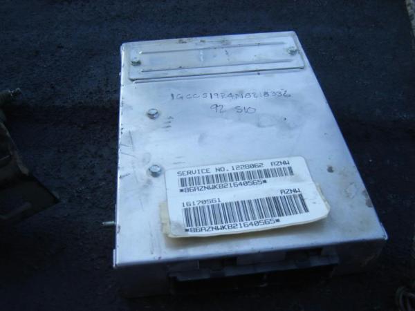
- ECM
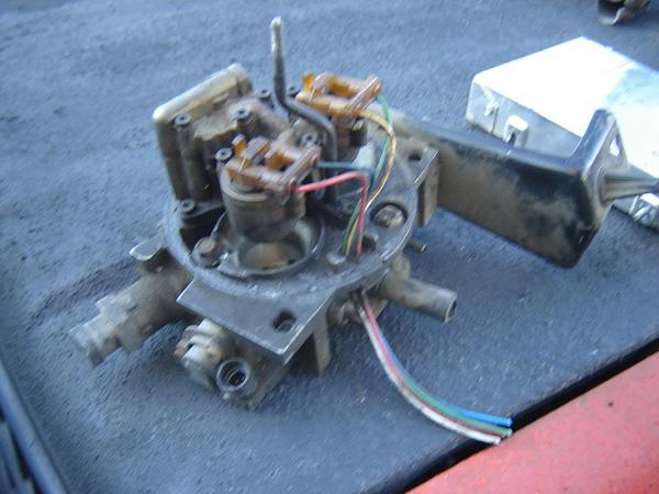
- Throttle body
- Air filter housing
- TPS (throttle position sensor)
- IAC (Idle air control valve sensor)
- ECT (engine coolant temp sensor)
- Knock Sensor (optional)
- O2 (factory Ford 2.8 O2 will work)
- GM 2.8 distributor module (from under cap)
- EST (electronic spark timing) Module
- Coil
- Fuel Pump Relay
Parts from an ’80s F-150:
- Electric fuel pump
Universal Parts:
- Rubber fuel line
- 2x universal relays
- Distributor from a Duraspark 2.8
- TBI to 2BBL adapter plate (and gaskets)
- Fuel filler neck from ford explorer (for adding in return line)
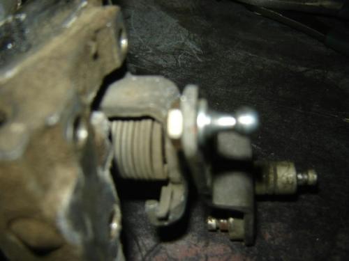
- Throttle cable linkage ball from carburetor (can be purchased from parts store, or taken from carburetor)
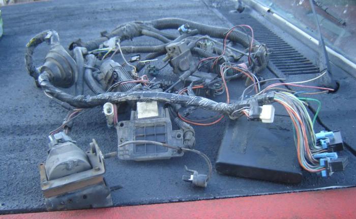
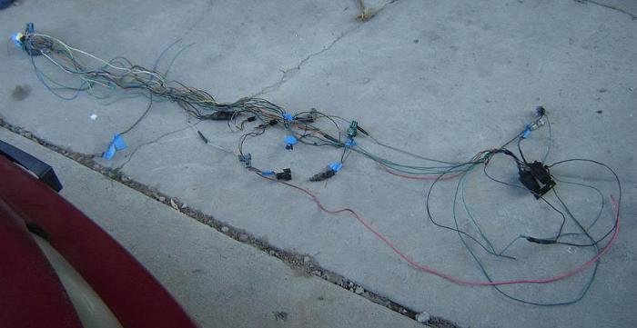
We went to the Junkyard and pulled the parts out from the donor vehicle
the parts-pile looked like this:
Pinout: We used the ECM pinout that has been preserved HERE.
To weed out the unneeded wires, and consolidate the harness:
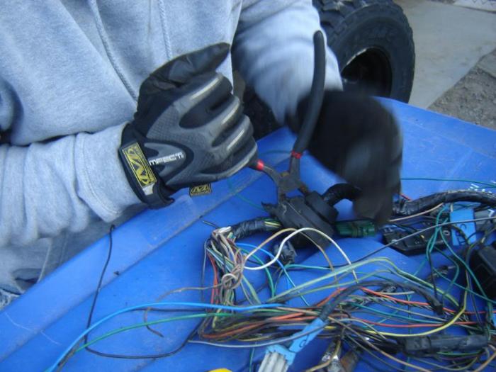
The wires needing to be spliced:
1. battery 12 +
2. switched 12v +
3. negative
4. fuel pump relay
5. O2 sensor
6. “crank” signal
Wire connectors not needing to be spliced:
1. ECT
2. IAC
3. TPS
4. EST module
5. fuel injectors
6. distributor module (7 pins total, we spliced ours anyway to clean up length)
7. MAP (manifold absolute pressure) sensor, which is usually mounted to the GM air cleaner if you want to use the gm air cleaner housing
8. knock sensor
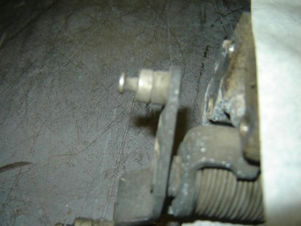
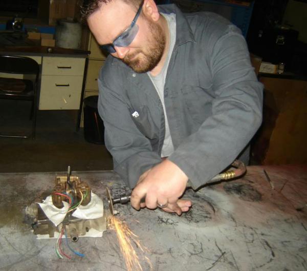
You need to grind the back of the rivet off on the TBI linkage. Once you have ground the rivet off the post will come off and leave a hole for your ball “nub”
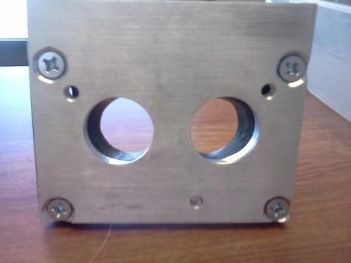
We then made the TBI adapter plate:
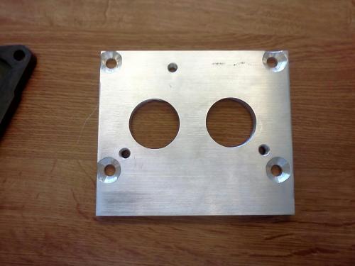
The spacing of the holes is slightly wider on the GM TBI
The modified Phenolic spacer:
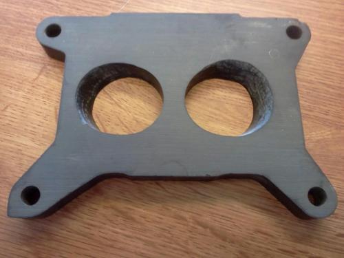
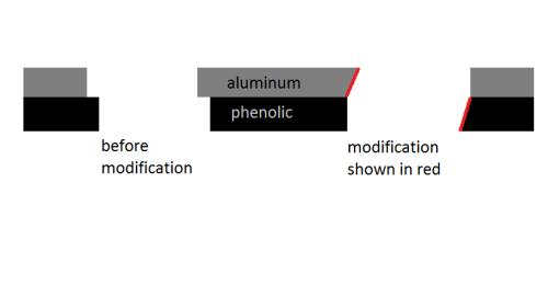
The gradual modification on the top spacer:
With them loosely bolted together:
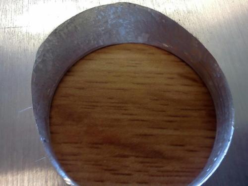
A cross-sectional view of how I used a die-grinder to modify the spacers. On the left is how the overlap was, on the right shows how I took material off; One side of each spacer to channel the air flow smoothly, the difference was less than 1/4″. Before criticisms fly, I deliberately left the finish rough with the die-grinder to promote atomization.
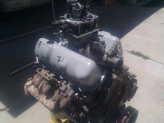
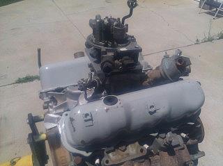
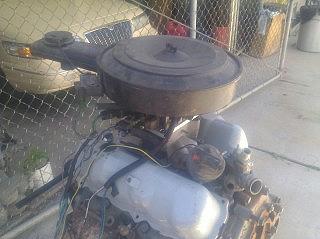
Mocked up on a loose engine:
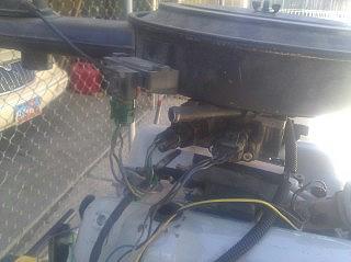
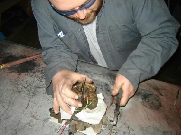
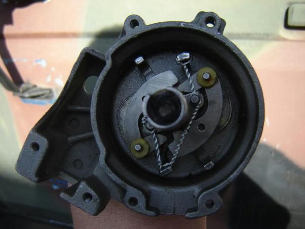
Next is the distributor, the way it needs to be wired to the GM distributor module like this:
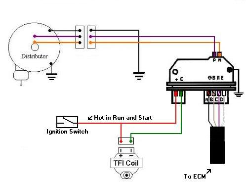
We did not use the TFI coil, we used the GM coil which was already wired in. If you wanted to use the TFI coil you could wire it the same way.
We wanted to utilize the GM Electronic Spark Timing control, in order to do that we needed to disable the mechanical advance inside the distributor, and to disconnect the vacuum advance. If you don’t do that the ECM would try to “double advance” the timing.
Using the GM EST made the most sense because there is not a proper port on the TBI that has venturi vacuum to properly actuate the vacuum advance on the distributor. Vacuum advance will not function properly on mere manifold vacuum.
Rico used safety wire, but a small tach-weld on the weights to immobilize them, anything will work, you don’t need to remove the distributor to do this if you don’t want to mess with your timing.
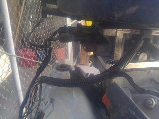
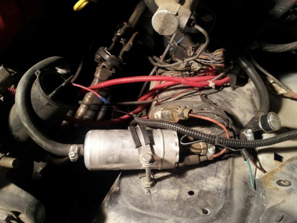
Next comes the fuel pump(s). What we did was use the factory Ford 2.8 mechanical fuel pump to draw the fuel from the tank, and feed the high pressure pump, which we just put under the hood.
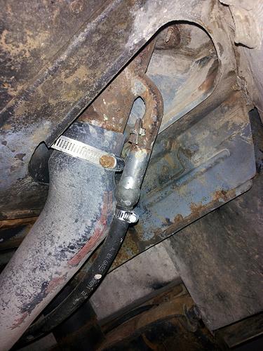
This is how the return line is ran. (Ford explorer filler neck which bolts in)
We spliced the O2 sensor into the wire on the harness.
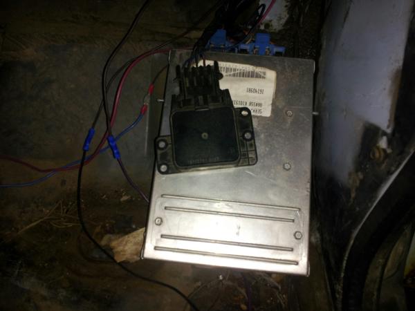
The distributor module needs to be mounted to a heat sink in order to prevent premature failure.
Rico made this heat sink as over kill to prevent failure (which caused the demise of our first module)
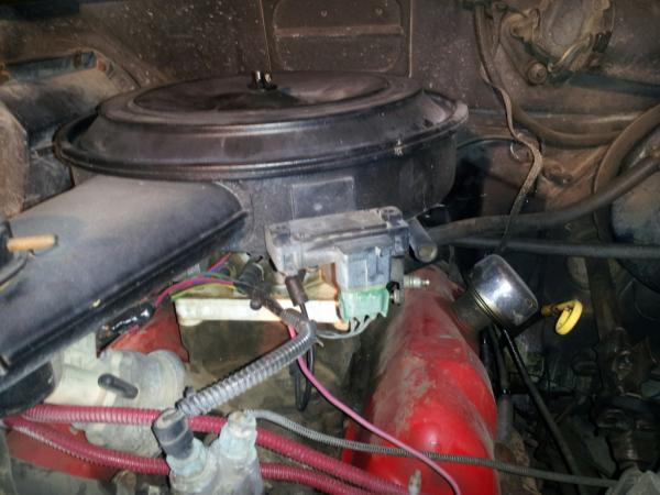
The GM air filter housing, with attached MAP sensor
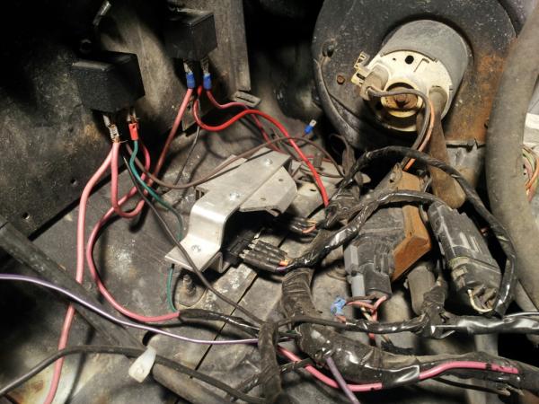
We mounted the EST module near the ECM under the dash.
Here are our (2) universal relays that we used, one is for the system power, the second is the fuel pump relay.
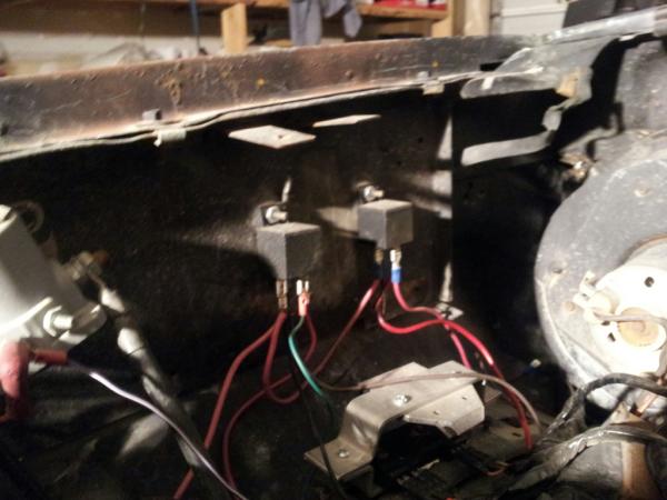
The system power relay uses the switched ignition as a trigger, and the output goes to the ECM.
The fuel pump relay uses the green/white wire from the ECM as a trigger and the output powers the electric fuel pump.
The ECM uses a signal from the ignition switch to know when you are trying to start. We ran this wire (purple/white) to the post on the starter relay to get the “crank” signal.
The knock sensor needs to be threaded into the pipe thread fitting on the block (antifreeze drain), or on cylinder head If you choose to utilize the knock sensor. It will also retard timing in the event of pre-ignition, we chose not to use it.
I have been driving this for a couple months since we finished. The only problem was from not mounting the distributor module to a heat sink. No problems have been seen since we added a heat sink.
There is an “EST bypass” which when disconnected allows you to set timing that goes to the distributor module.