
Introduction:
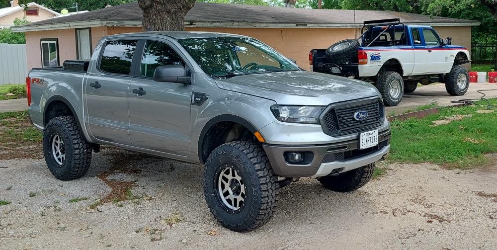
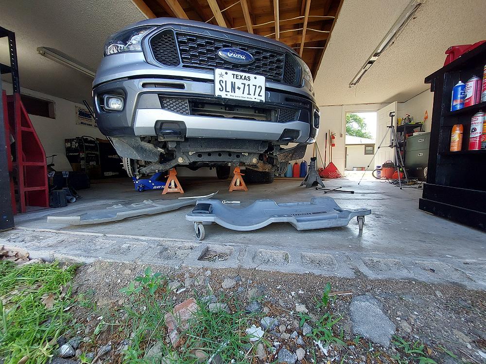
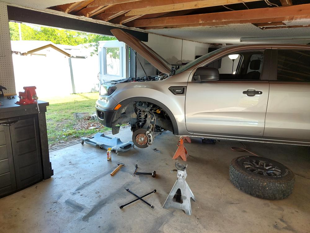
I have been using and promoting Skyjacker Suspension since the late 1990’s. When I built the TRS-2 1996 Ford Ranger in 2004, I installed a Skyjacker Class II 6-Inch suspension kit on it that included longer radius arms and new Softride replacement rear leaf springs. That Ranger can be seen in the photo above behind my 2021 Ford Ranger. I still use that Ranger and the same suspension on it today, almost 20-years later.
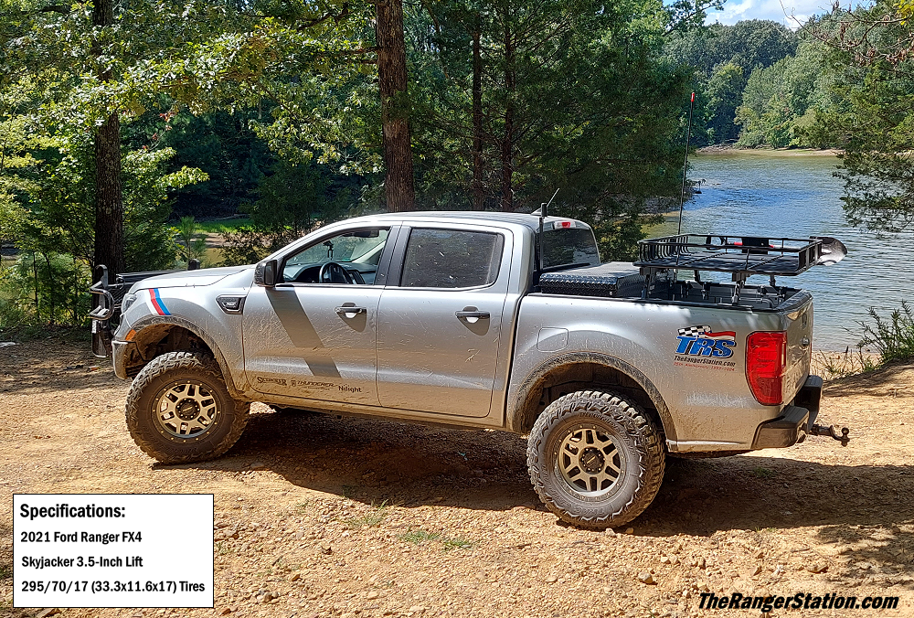
When I purchased my 2021 Ford Ranger FX4 to become TRS-3, I looked at the different suspension kits available, and then contacted Skyjacker about their 3.5-Inch lift kit. Having used and promoted their product for a long time, I was fortunate enough to get them to donate one of their kits to my build. If they wouldn’t have offered to give me one, I would have bought it anyway, so don’t think I’m just promoting this kit because it was free.
Skyjacker actually offers (2) different kits for the 2019 and newer Rangers:
Kit FR20350P is for the cast steel OEM steering knuckle.
Kit FR19350PA is for the aluminum OEM steering knuckle.
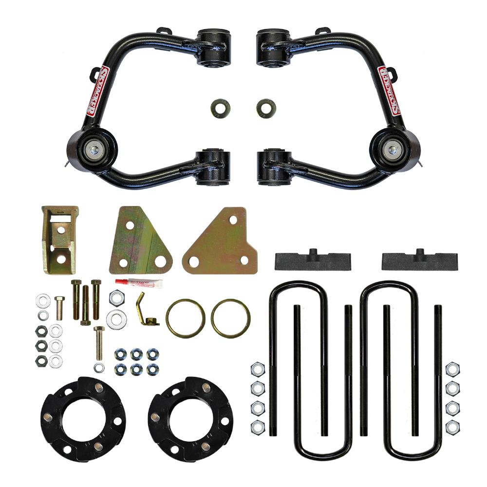
The Kit Components:
Link: Skyjacker 3.5-Inch Lift Kit For 2019+ Ford Ranger 4×4
Installation Instructions .pdf File: Skyjacker 2019+ Ford Ranger 3.5-Inch Lift Instructions
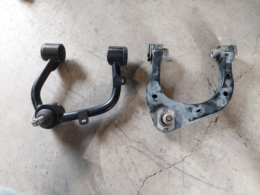
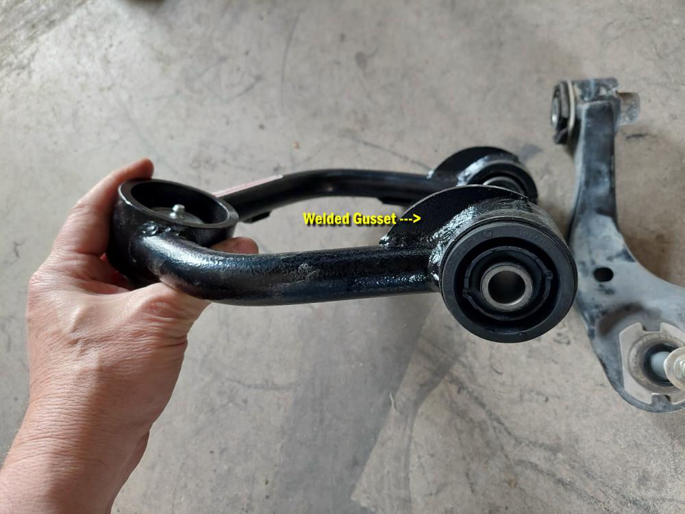
The 3.5-Inch kit comes with beefy new tubular upper control arms made from high weld strength, thick-walled DOM steel tubing to withstand extreme amounts of stress and loads. For additional rigidity and strength, a welded gusset plate stiffens the arm and bushing eyelets into one.
The replacement UCA comes completely preassembled and ready to install with a durable powder coat finish. The steel encased OEM style rubber bushings deliver a quiet consistent controlled stability and smooth riding comfort. The greaseable ball joint’s full induction ball design, low friction bearing technology and other technical performance characteristics add longevity and increased strength.
The spacer is made out of 3/16-inch steel plate (no nylon or aluminum) with the studs welded in place. Other kits require you to install the studs into the spacer during assembly.
The factory leaf springs remain and a 1.25-inch block and U-bolt kit raises the rear.
NOTE: Designed To Fit Models with OEM Aluminum Steering Knuckles. Not Designed to be Used on Models Equipped with Tremor Offroad Package.
Important Notes:
If Larger Tires (10% More Than OEM Diameter) Are Installed, Speedometer Recalibration Will Be Necessary. Contact Your Local Ford Dealer or an Authorized Skyjacker Dealer for Details.
Maximum Tire Size: 285/65R18
After Installation, a Qualified Alignment Facility Is Required to Align Vehicle to OEM Specifications.
Not Designed to be Used on Models Equipped with TREMOR Off-Road Package.
Aftermarket Wheels Must Have a Minimum of 93.1mm Center Bore & Maximum 6.5-inch Backspacing.
Wheels with Less Than 6.50 Inch Backspacing May Require Slight Trimming.
Nine (9) Inch Wide Wheels Will Require Trimming.
MAKE Sure You Have Ordered & Received Correct Lift Kit. (They Will Not Interchange.)
# FR19350PA Aluminum OEM Steering Knuckles.
# FR20350P Cast Steel OEM Steering Knuckles.
Front Installation:
NOTE: Save all factory components and hardware for reuse, unless noted.
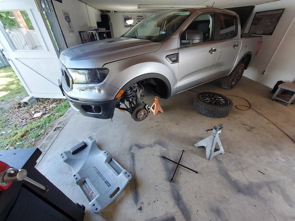
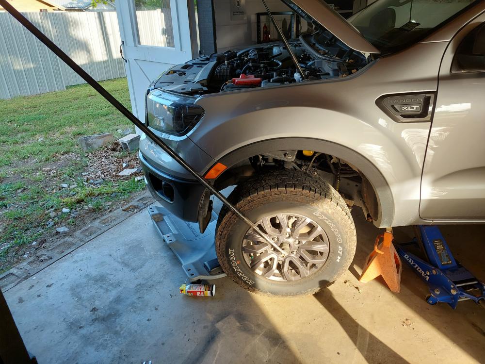
I jacked the Ranger up, placed heavy duty jackstands under the frame under the front of the cab, set the parking brake, and removed the front wheels.
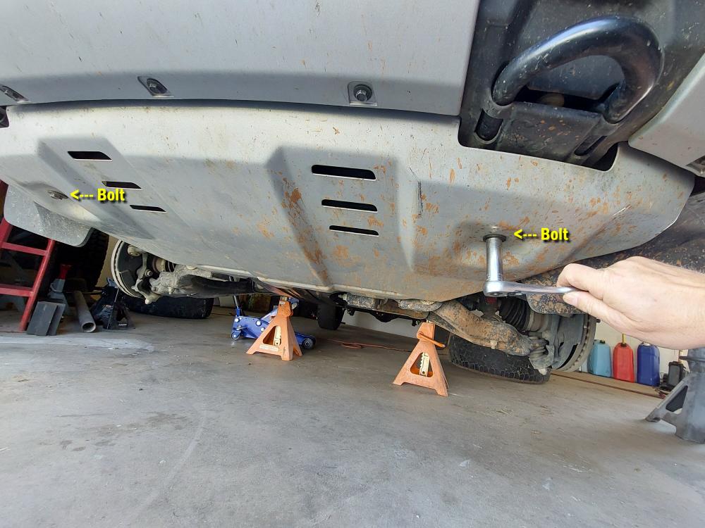
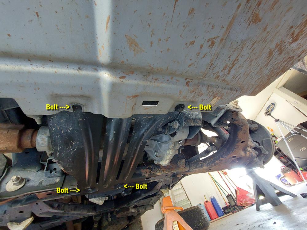
I removed the bolts for the skid plates with a 15mm socket.
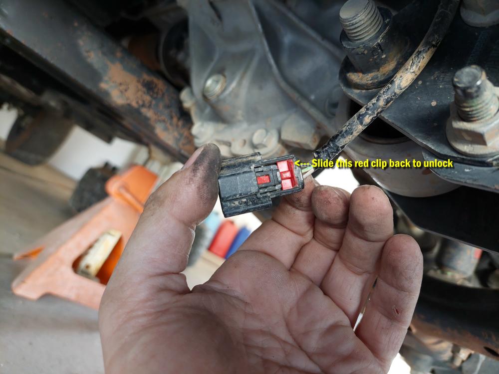
Next I had to unplug the (3) Electric Power Assist Steering (EPAS) connectors.
NOTE: A sudden jar of a hammer blow or impact wrench to other suspension components could cause contacts of EPAS internal power relay to arch or short out.
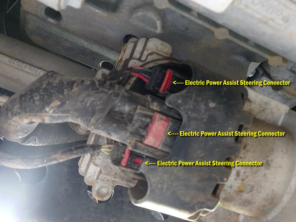
These connectors have a red plastic locking clip on them that need to be gently pulled back to unlock the connector before you can remove it.
CAUTION: Do not break the locking clip or the connector itself!
I sprayed a little WD-40 on the red locking clip and gently worked it backwards to unlock the connector.
Next disconnect the (2) ABS wire plastic clips from the Upper Control Arm (UCA) with a plastic fastener removal tool.
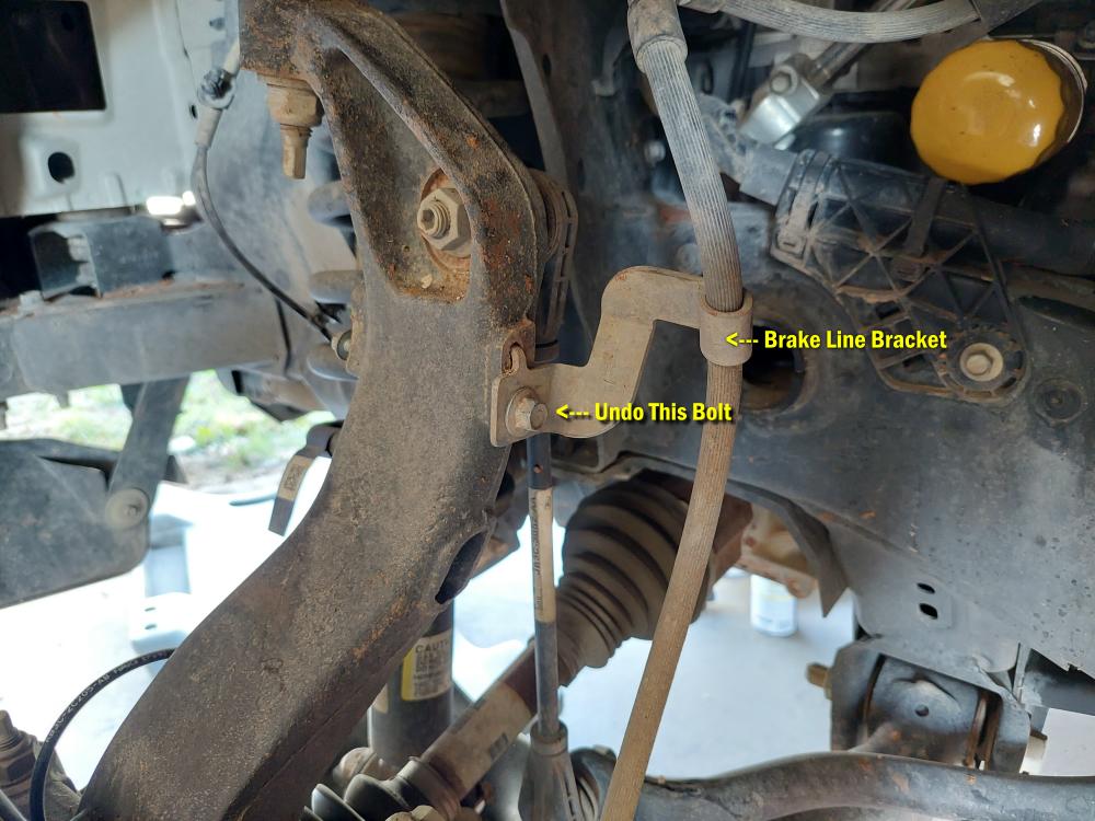
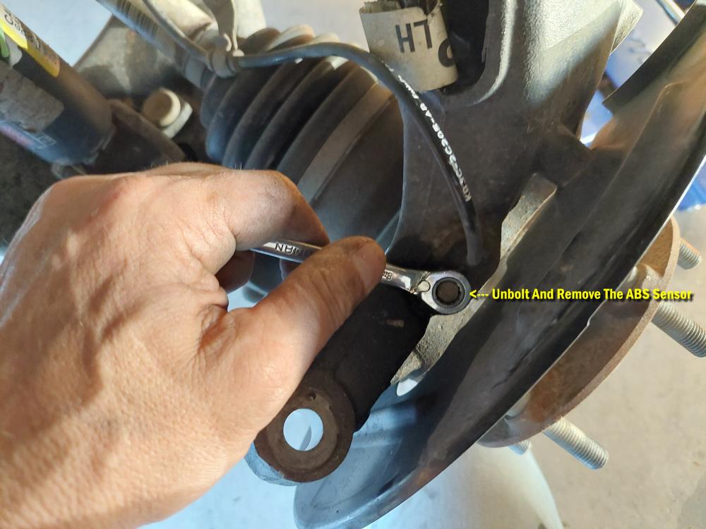
Then disconnect the ABS sensor bracket from forward side of the knuckle with a 8mm socket \ wrench and the brake line bracket from rearward side of the knuckle with a 10mm socket \ wrench.
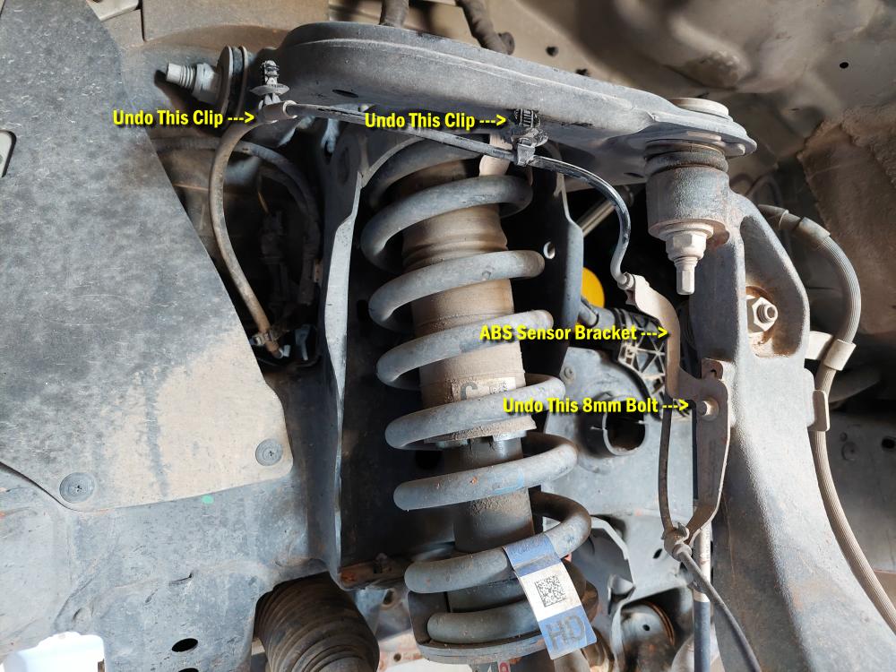
Remove the ABS sensor from the knuckle.
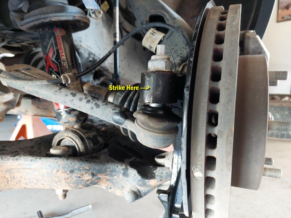
Loosen, but do not remove the tie rod nut from the knuckle using a 21mm socket \ wrench. Unseat the tie rod by striking the tie rod boss of knuckle at tie rod end to dislodge.
NOTE: ONLY strike knuckle portion. Remove nut and remove tie rod end from knuckle.
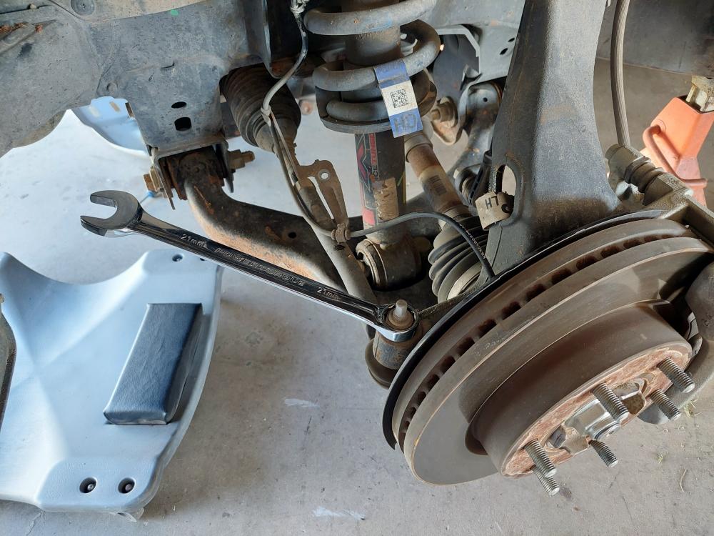
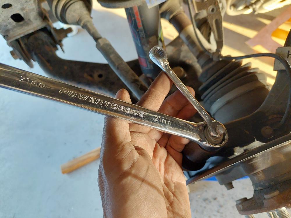
Then remove the tie rod. I used a 8mm wrench to hold the joint while I removed the nut with a 21mm wrench.
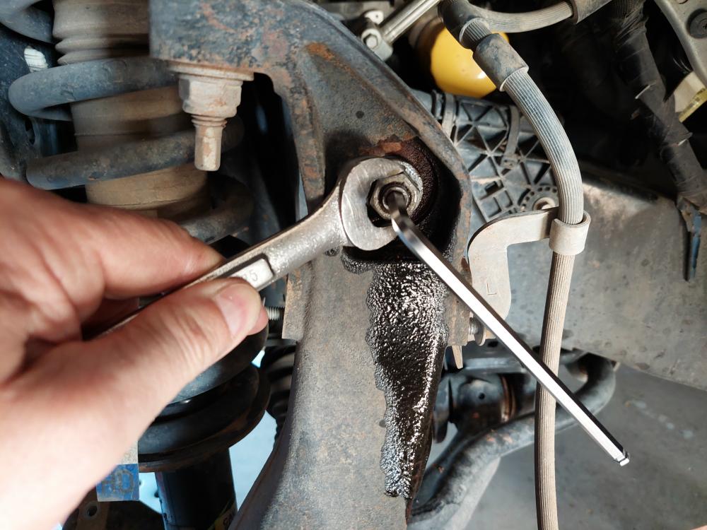
Use a 18mm wrench to remove the upper sway bar link from the knuckle. I had to use an Allen wrench to hold the joint while I loosened the nut.
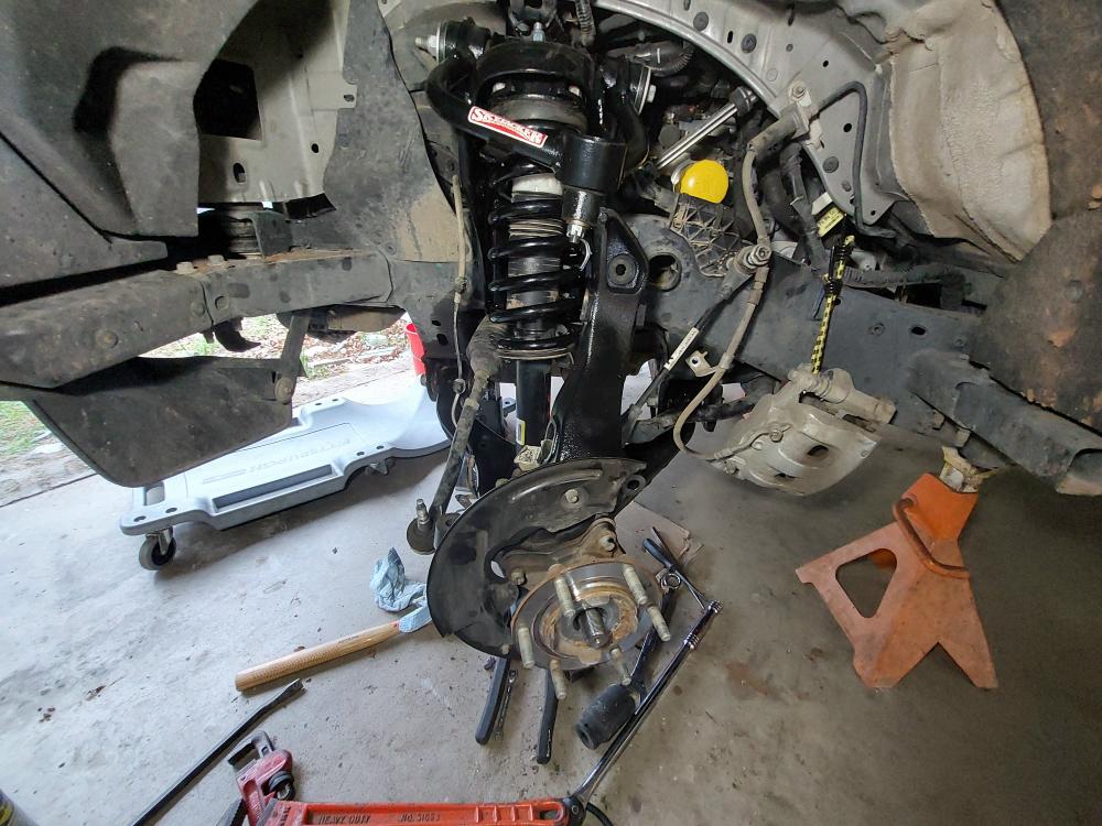
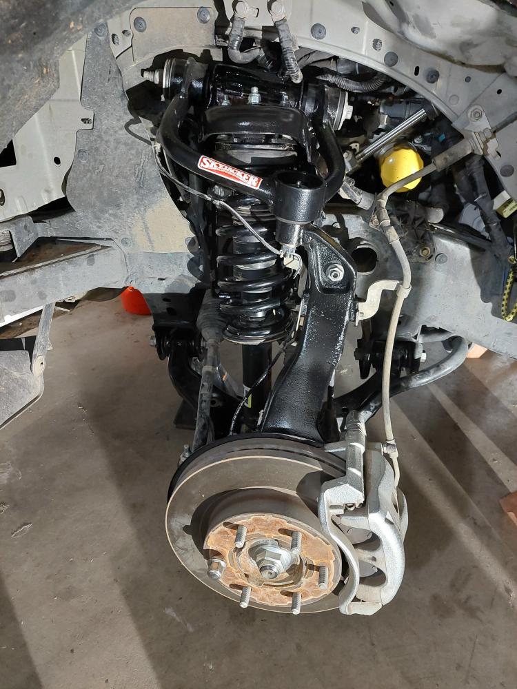
Disconnect the brake caliper from the knuckle using a 18mm socket \ wrench. Remove the brake rotor from hub and set aside. Do Not hang the brake caliper by the rubber brake line.
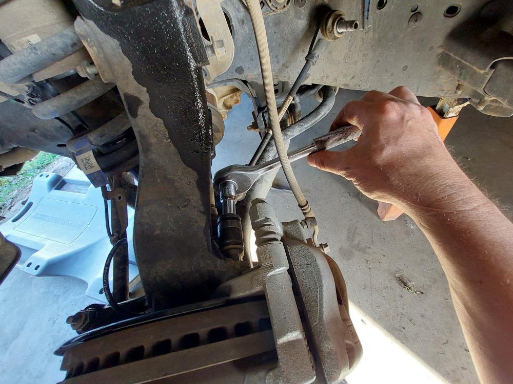
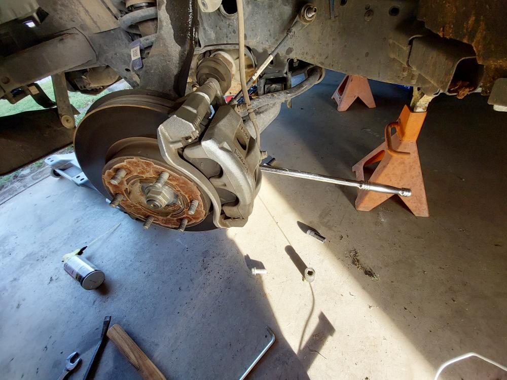
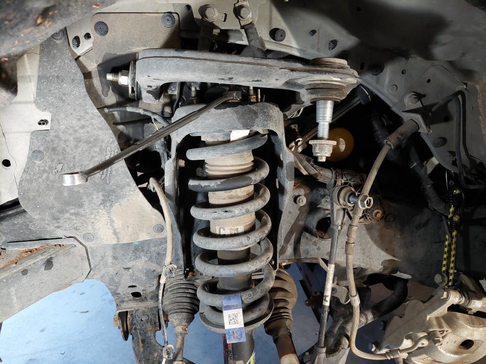
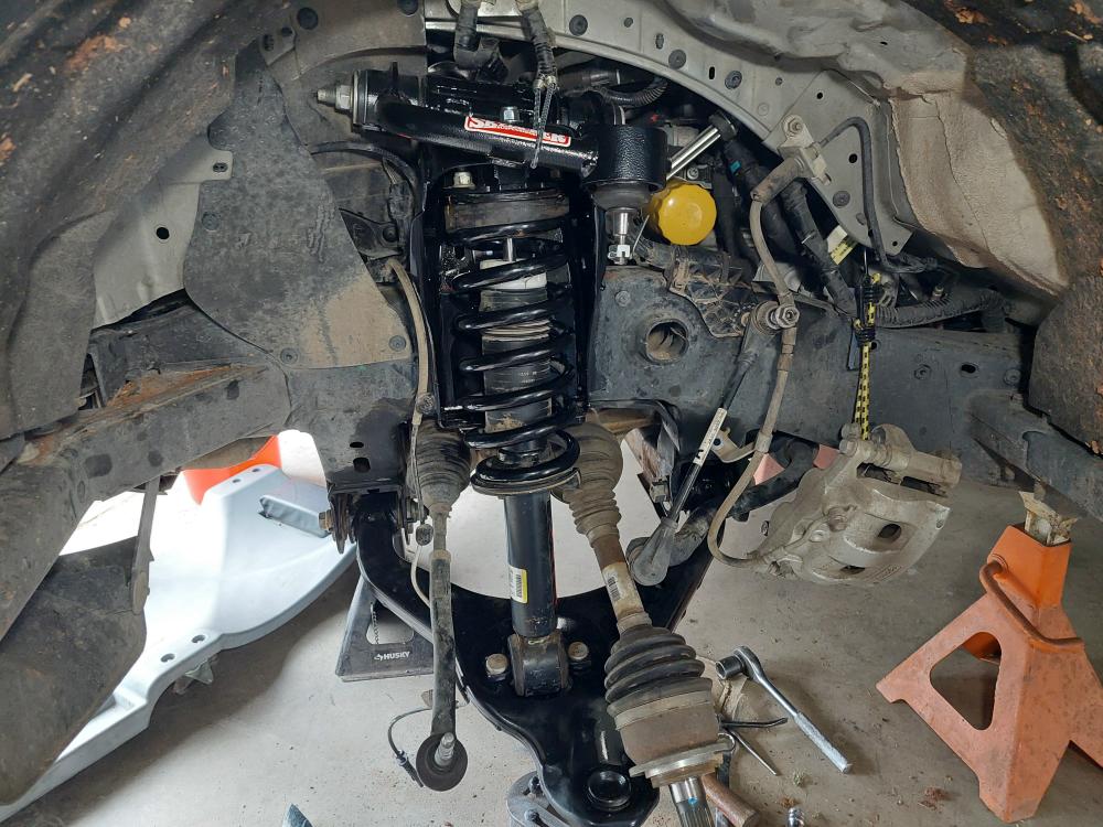
I hung the brake caliper from the body using a small bungie cord. See the photo below.
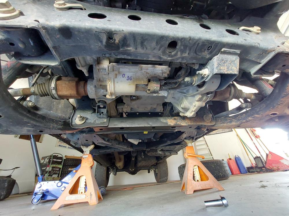
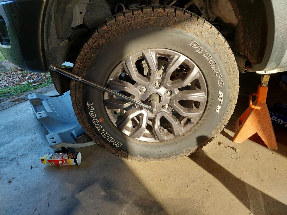
I had to remove the axle nut and I didn’t have an impact, so I removed the center cap from a wheel, mounted it back on the hub, lowered it to the ground so it couldn’t turn, and then used a 36mm socket on a breaker bar stuck into a pipe for leverage.
Once I got the nut broke loose I used my ratcheting breaker bar.

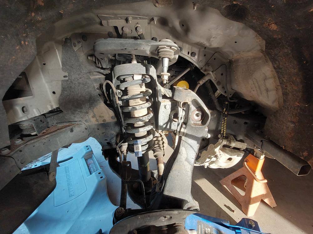
With the axle nut removed (and the tire) I supported the lower control arm with a jack and loosened the upper ball joint nut.
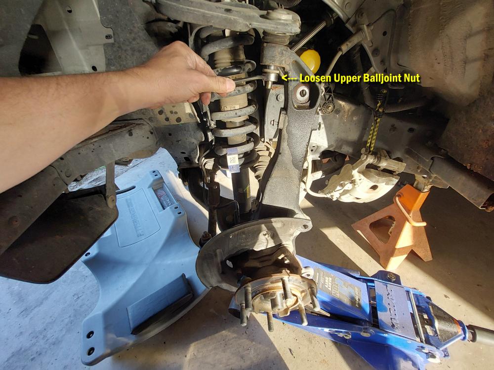
And then struck the knuckle with a ballpeen hammer to get it to drop loose.
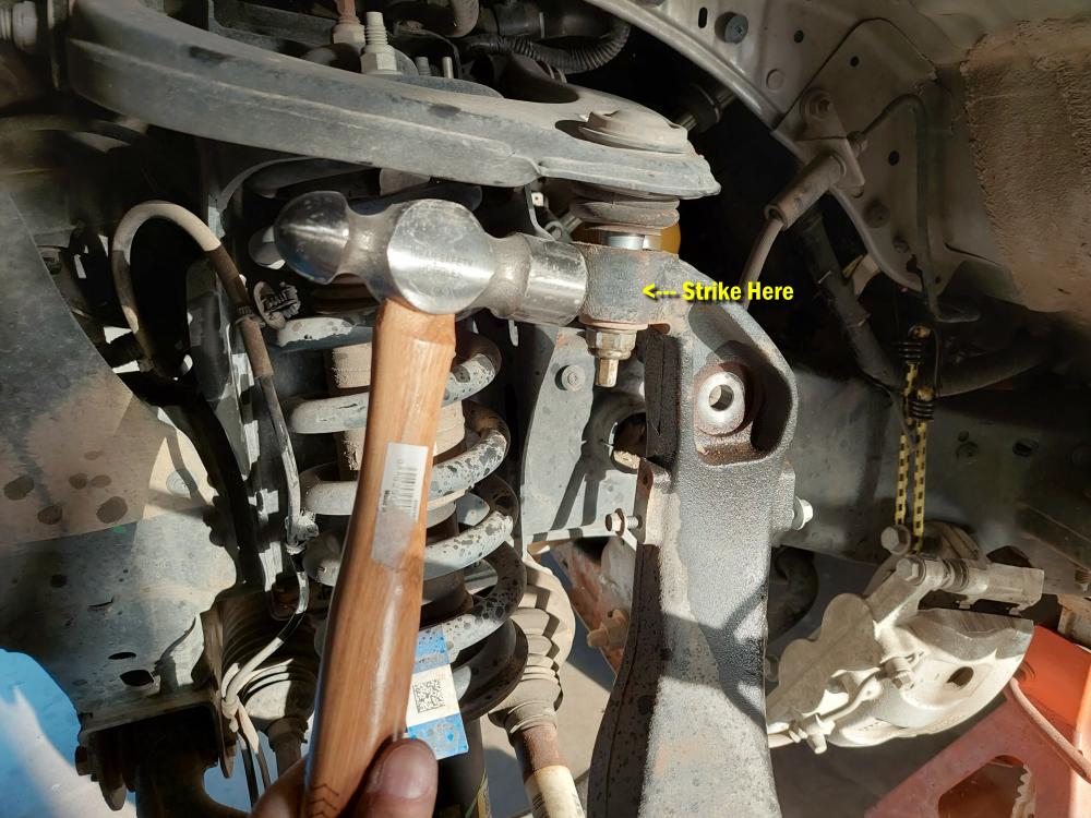
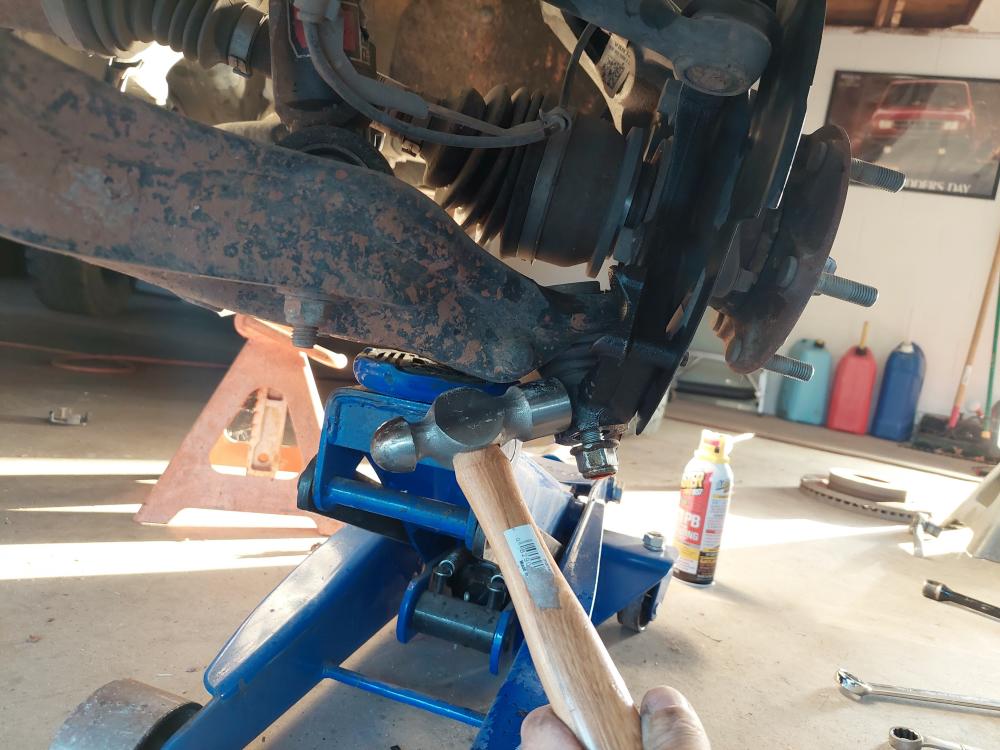
Next, I loosened the lower ball joint nut with a 21mm wrench.
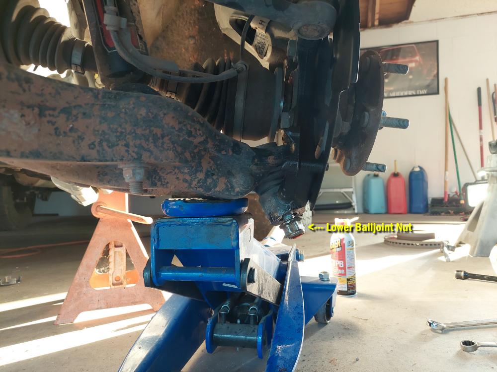
Again, I used a hammer to get the knuckle to drop loose.
Then I removed the knuckle.
Remove the (3) upper strut mounting nuts from frame mount using a 15mm socket \ wrench.
Remove the (2) lower strut mounting nuts from lower control arm mount using a 18mm socket \ wrench.
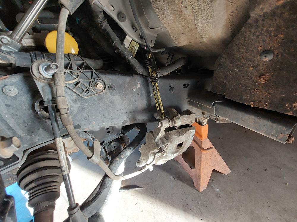
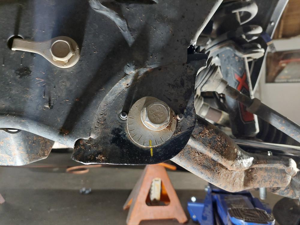
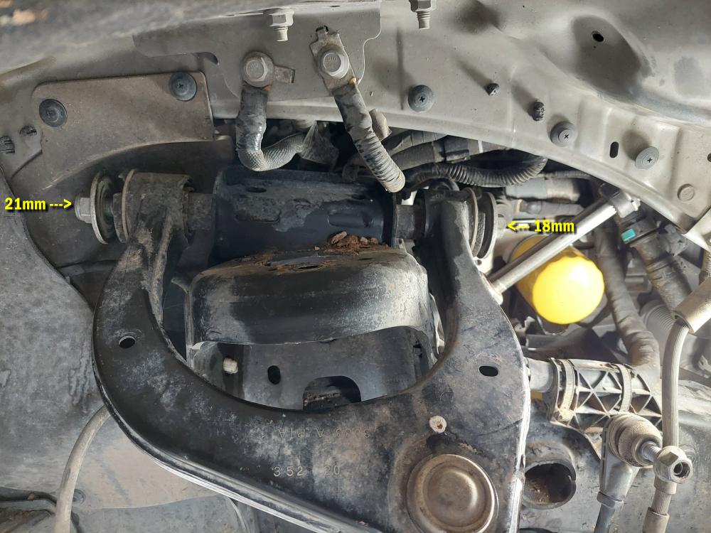
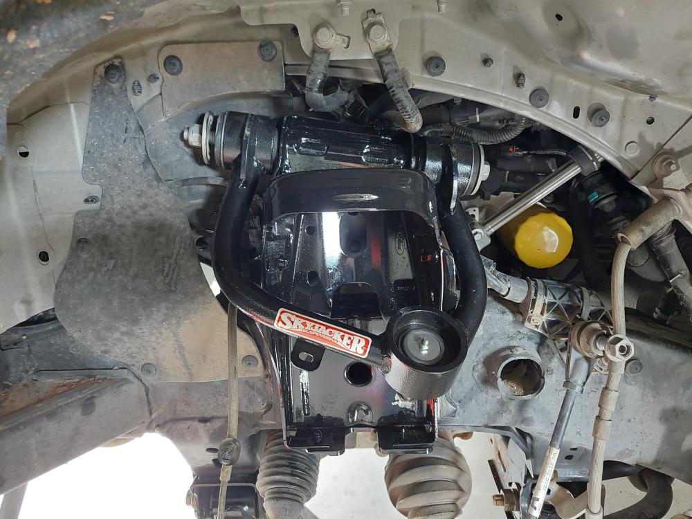
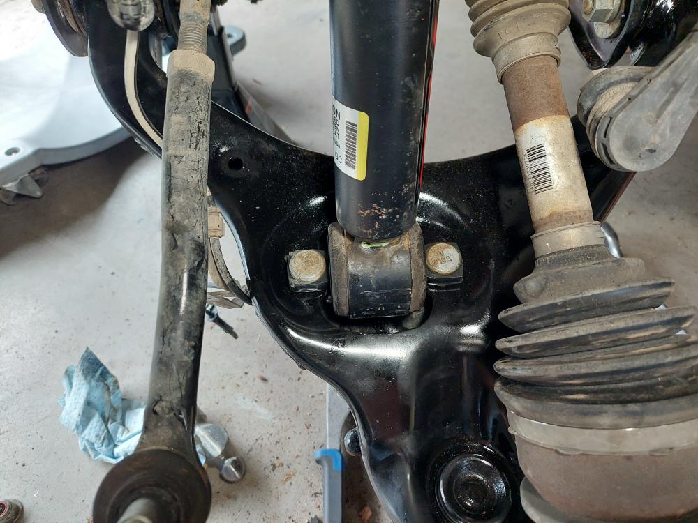
The instructions say to mark cam bolt position of lower control arm. Loosen, but do not remove the (2) cam bolts on lower control arm at frame using a 21mm and a 24mm socket \ wrench. Let lower control arm hang down.
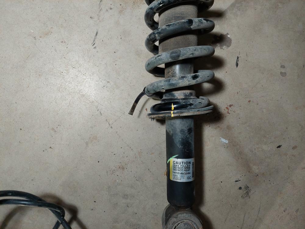
You can see in the picture below where I marked the cam with a yellow paint pen to keep the alignment.
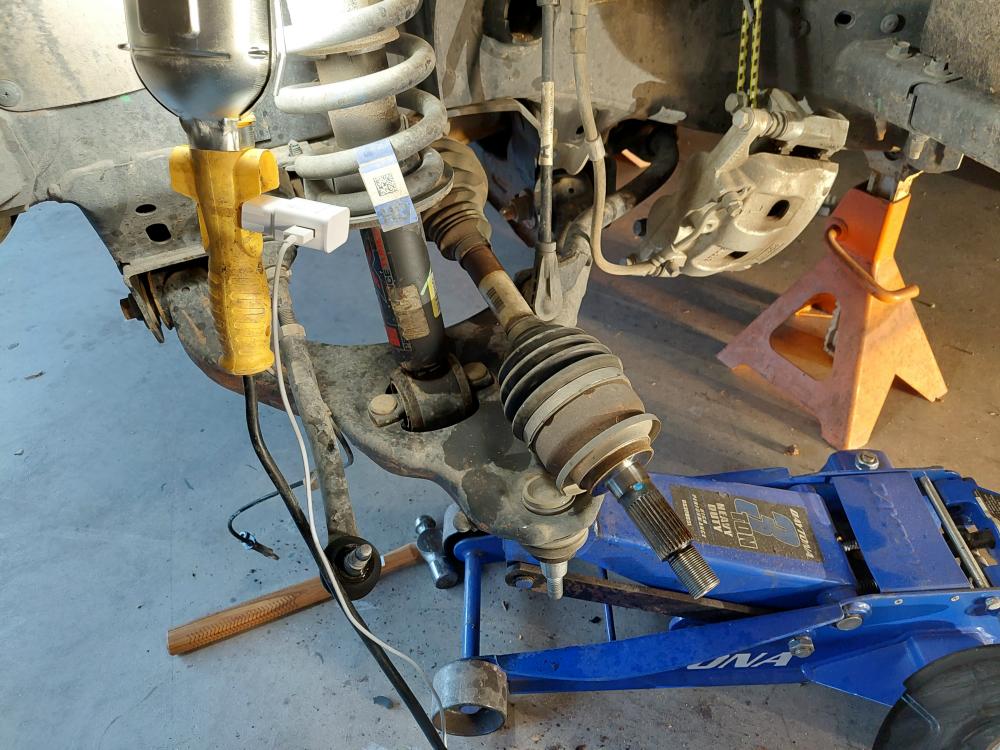
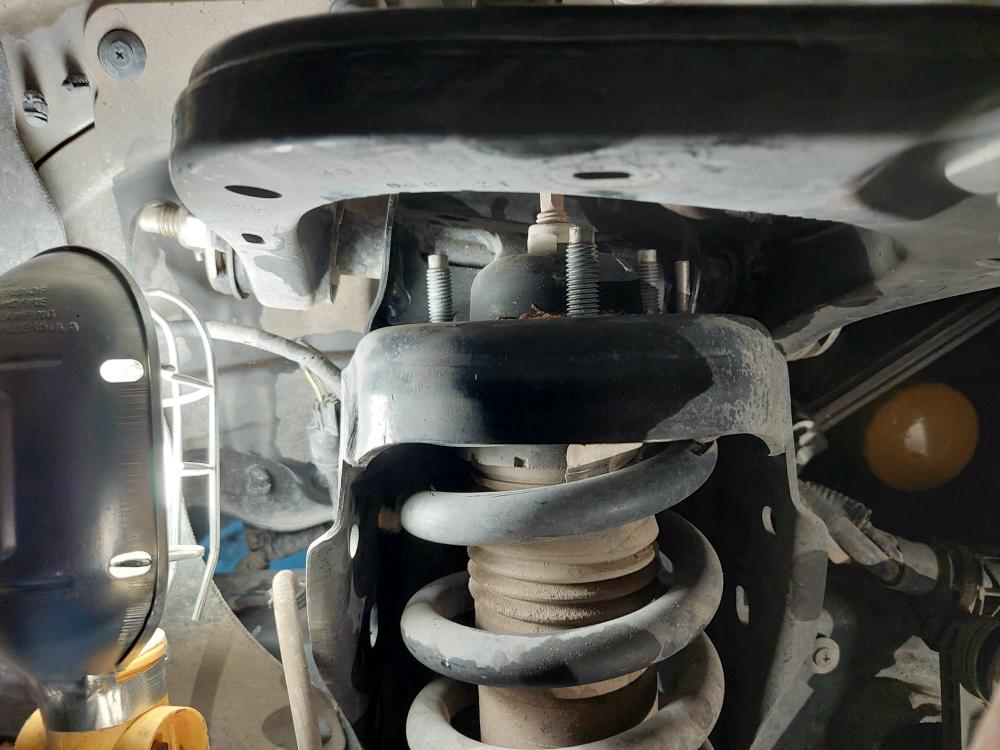
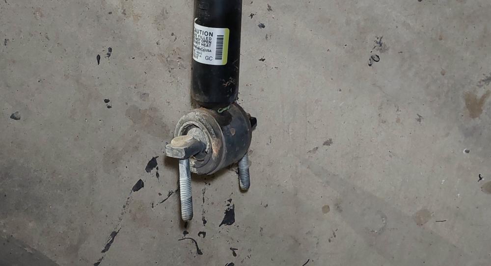
Advice / Experience #1: Loosening this will allow the lower control arm to drop down so you can get the strut out. The problem is that the lower strut mount is in a rubber bushing. If you look at the photo below, you’ll see that the mounting studs are angled a little to the right. This is the strut turned 180 degrees from its original mounting position, and this is the way it’s going to get re-installed. These studs and the part that goes through the rubber bushing are pretty much stuck in this position. I tried to loosen it up with some WD-40, but it didn’t allow me to move them by hand.
When I tried to re-install the strut, these studs would not line up with the mounting holes in the lower control arm. I ended up having to remove the lower control arm to mount the strut, and then reinstall the control arm.
So even though the instructions tell you to just loosen it, you’re probably going to end up completely removing it.
Advice / Experience #2: You will eventually have to cut the differential mount starting at Step 53 in the instructions. It would have been easier to cut that mount while I had the driver side lower control arm removed.
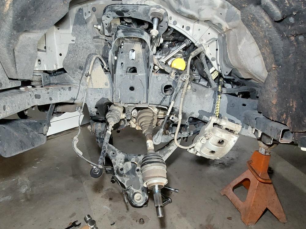
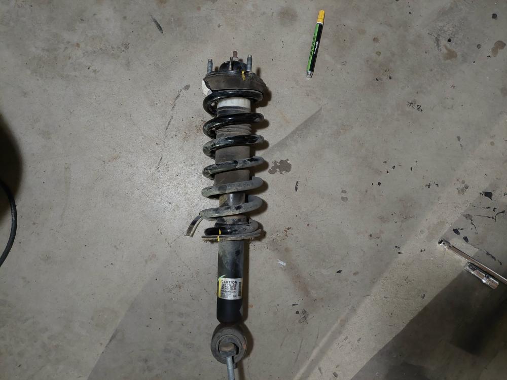
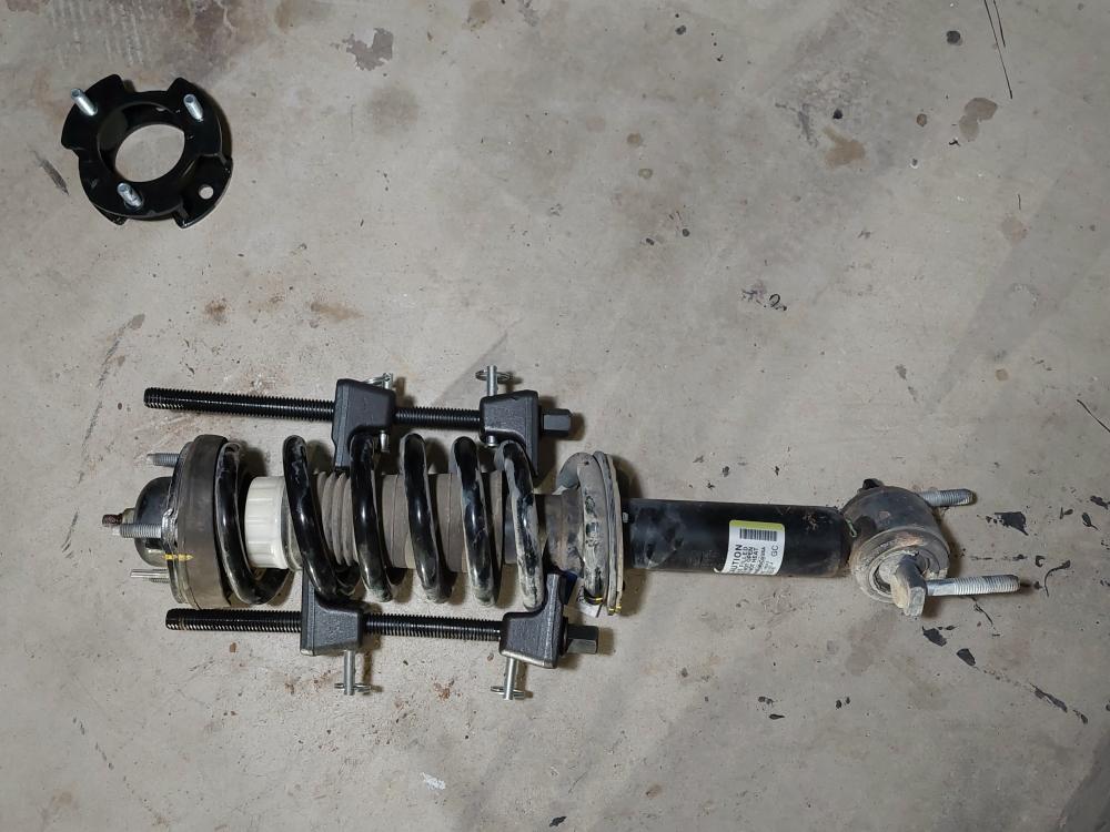
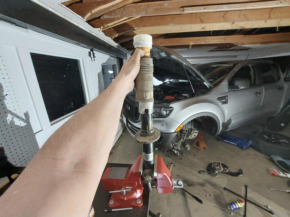
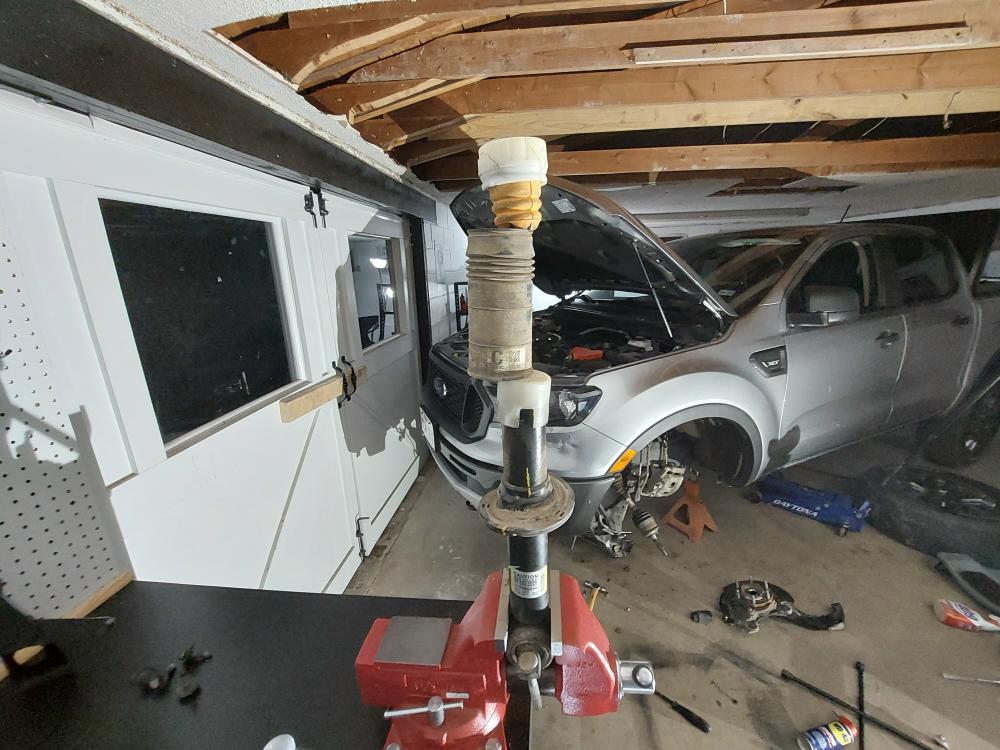
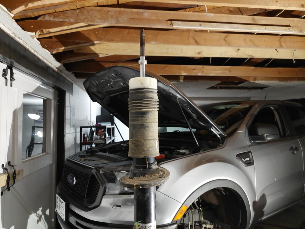
Here’s the strut removed.
Once the strut is removed you have to mark the pieces of the assembly with a paint pen to make sure they all line up when it goes back together.
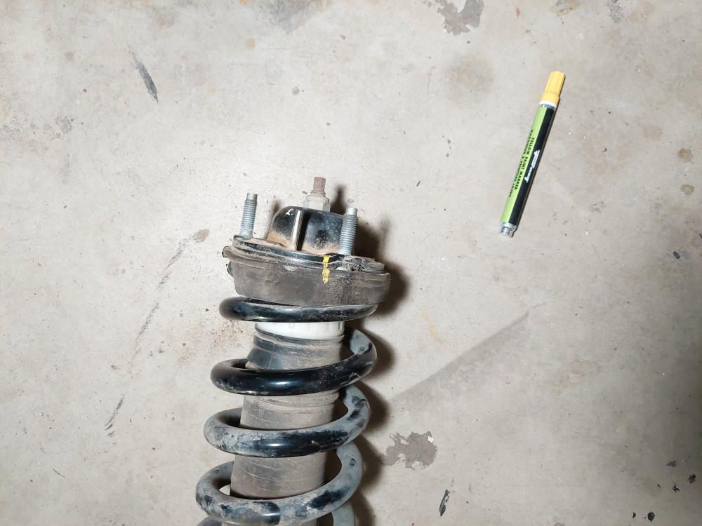
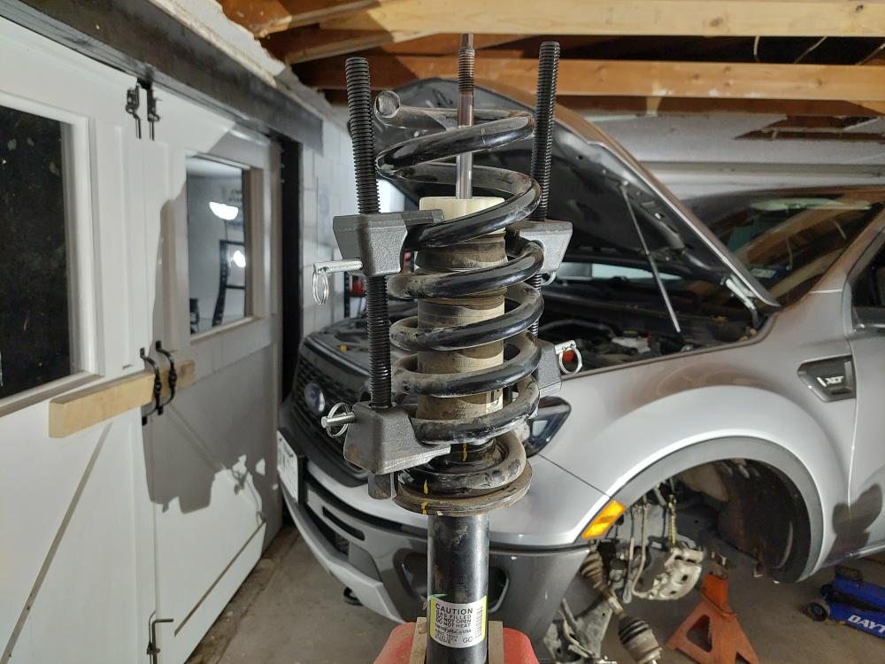
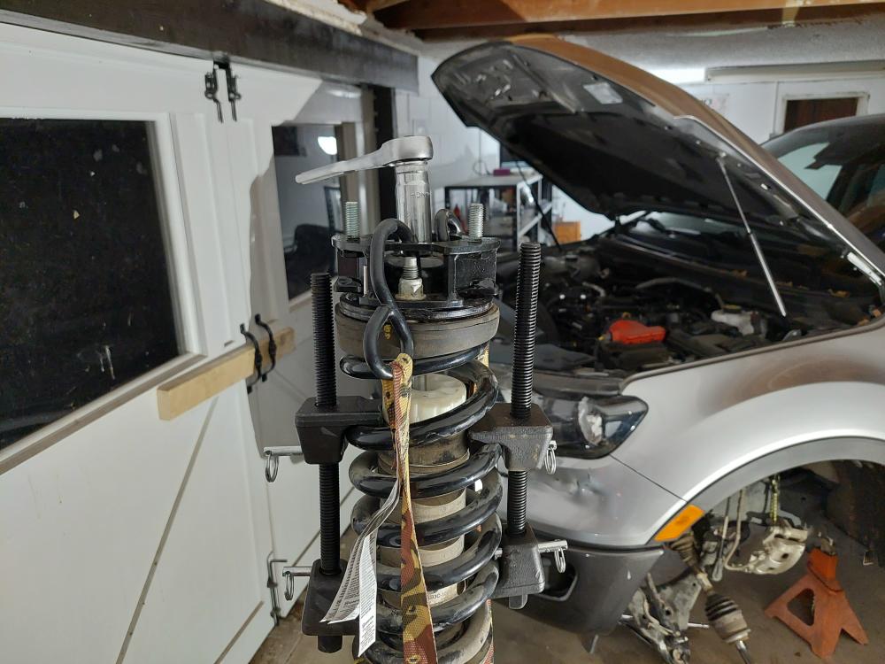
Then compress the coil spring with a strut spring compressor to relieve the tension from the strut top. I stuck it in my vice to make disassembly and reassembly easier.
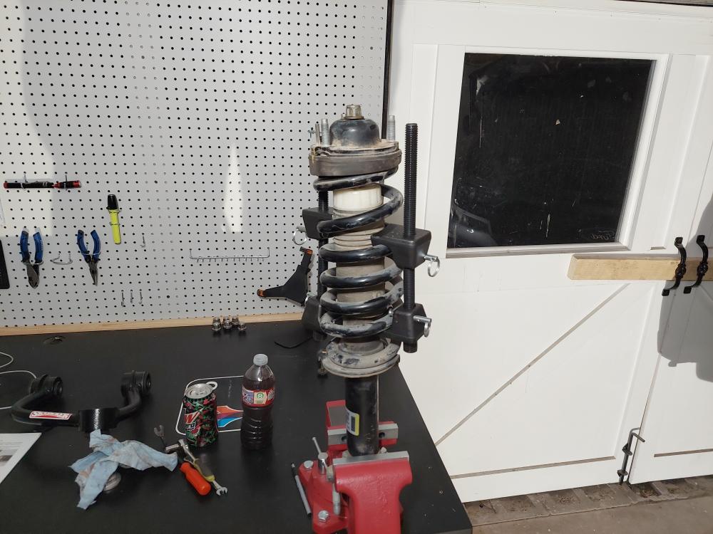
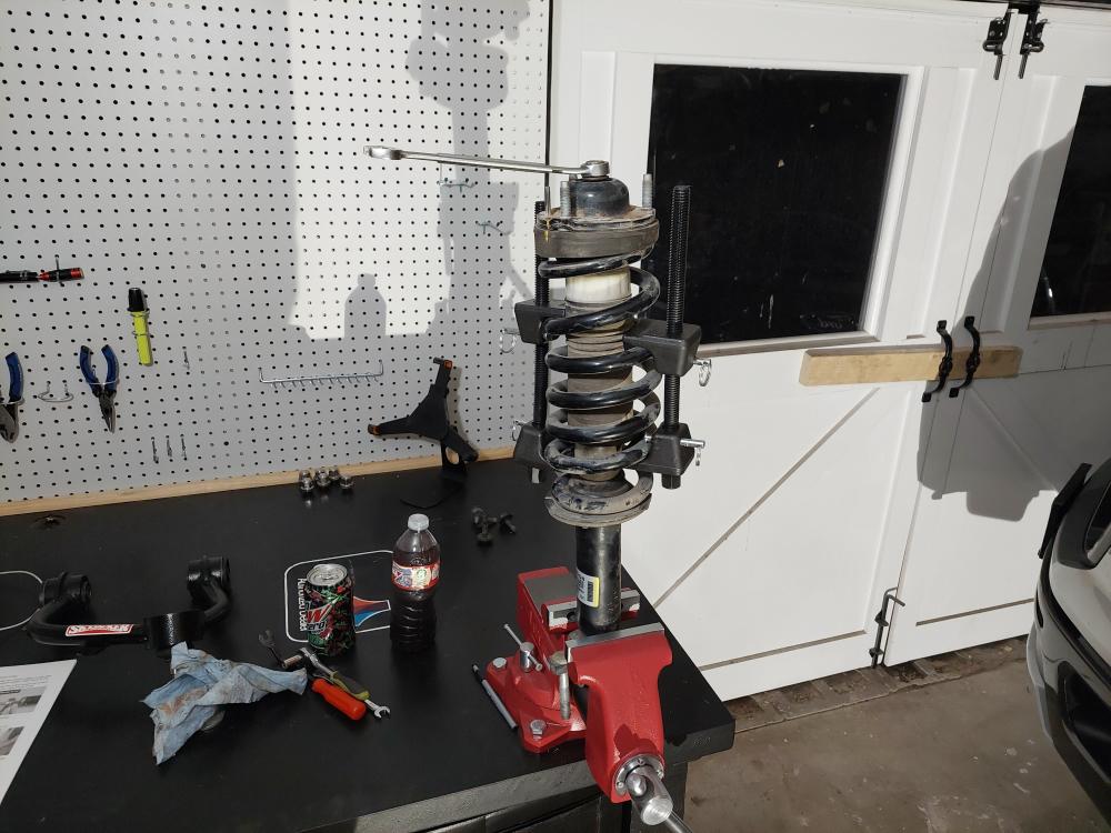
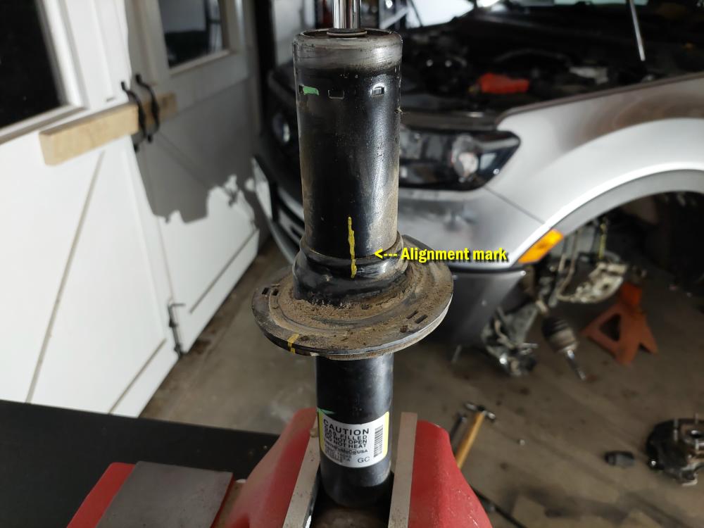
You can see that with the strut spring off I marked an alignment mark before removing the lower spring seat.
With all of the parts removed I installed the Skyjacker Strut Ring Spacer and then began reassembling the strut.
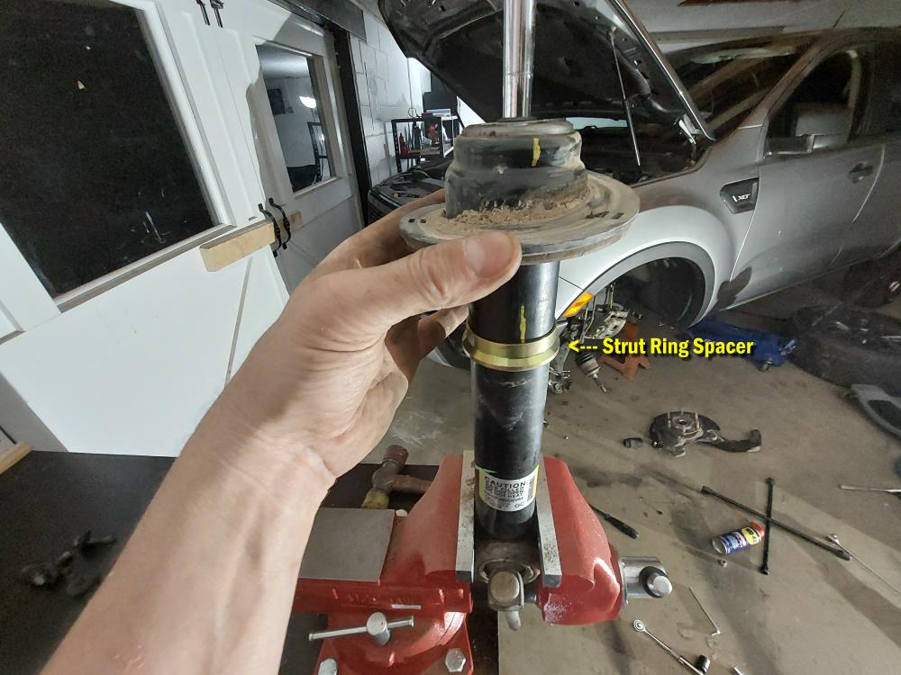
Making sure all of the alignment marks line up when reassembling.
I like that the Skyjacker spacer has studs welded into it where-as some kits require you to install the studs and pull them through tight when you tighten the nuts down.
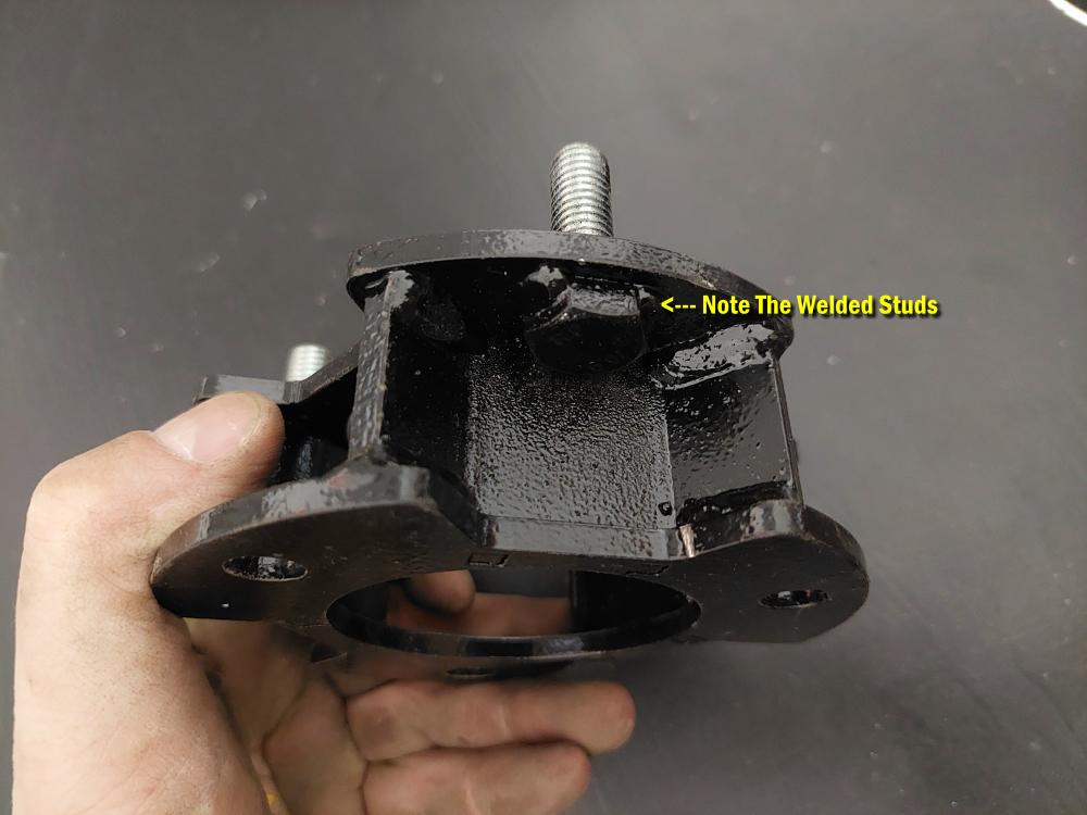
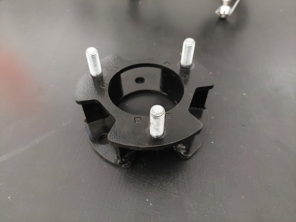
Below you can see the new strut spacer sitting on the strut. Since there are (3) studs and they have to be opposite of the factory studs to be able to sit on the strut, this will mean that the strut will be positioned backwards from its original position when installed.
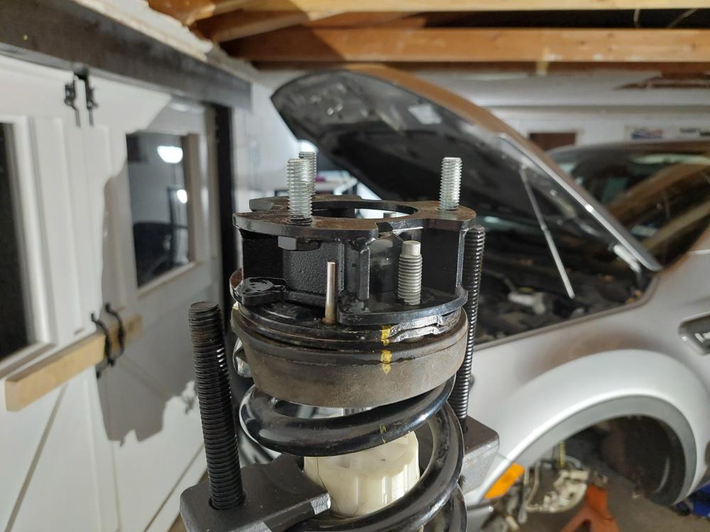
Here’s the strut spacer installed. I ended up using a ratchet strap going under the strut with the hooks up on the spacer to pull it down enough to get the center nut started.
Time to remove the upper control arm. Remove the upper control arm from the frame using an 18mm socket \ wrench and a 21mm socket \ wrench.
The factory upper control arm is replaced with this Skyjacker beefy control arm made from steel tubing. Note the welded gusset for added support.
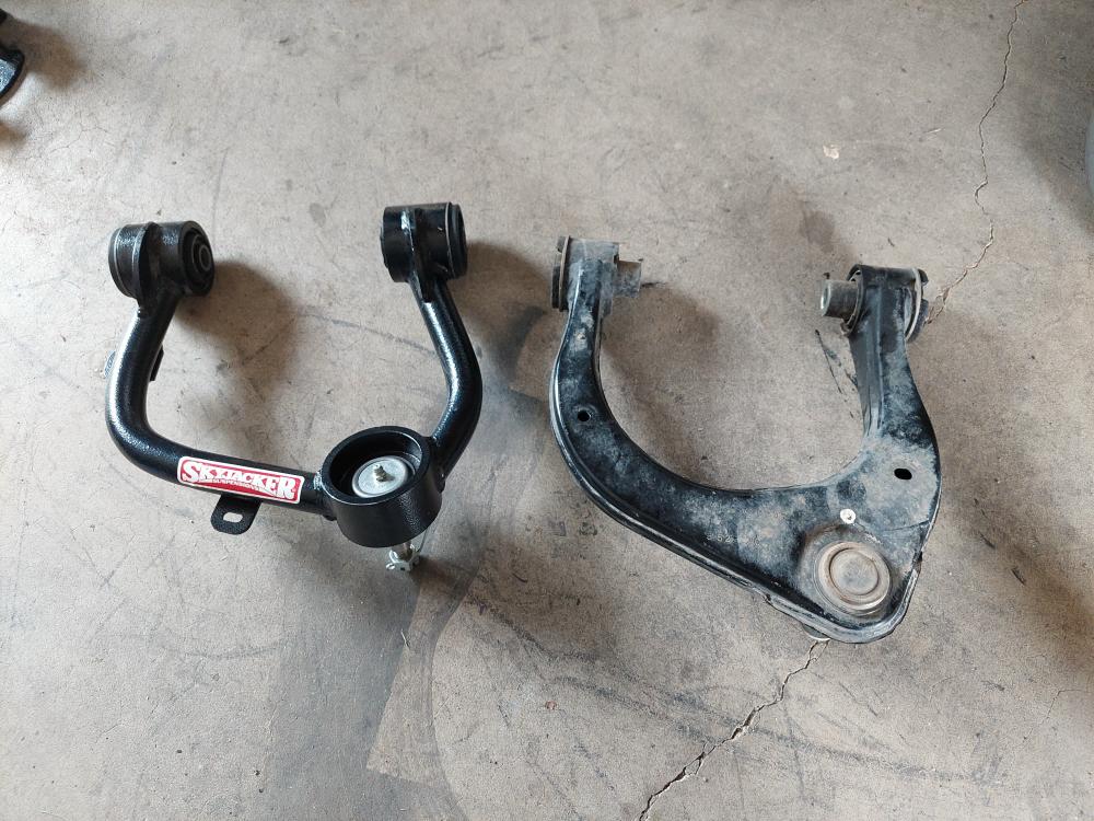
Install the new upper control arm with the factory hardware. Do not tighten it until the lift kit is installed and the truck is sitting on the ground with the full weight of the vehicle on it.
Install the upper strut mount and secure it with the new nuts using a 15mm wrench.
Install the lower strut mount with the factory nuts and an 18mm wrench / socket.
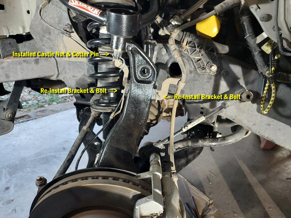
Re-installed the steering knuckle while making sure I guided the axle through the hub.
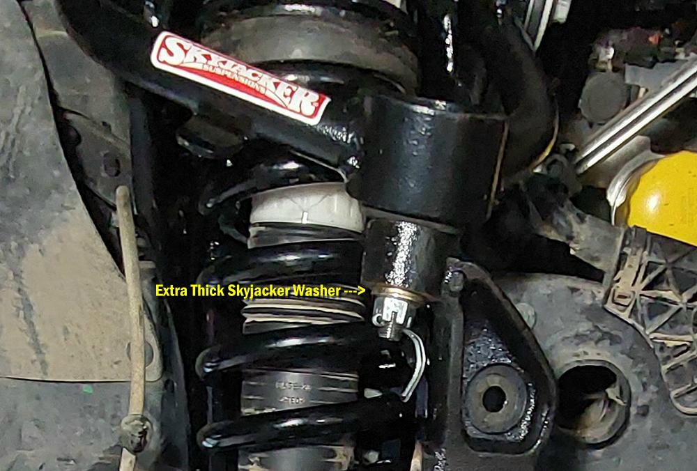
When installing the upper ball joint you have to use the extra thick spacer that comes with the kit and goes on before the castle nut.
Then install the lower ball joint.
Installed the axle nut. I’ll tighten it up when the wheel is on the ground just like I loosened it.
Re-installed the rotor and brake caliper. Use the supplied thread locker on the caliper bolts.
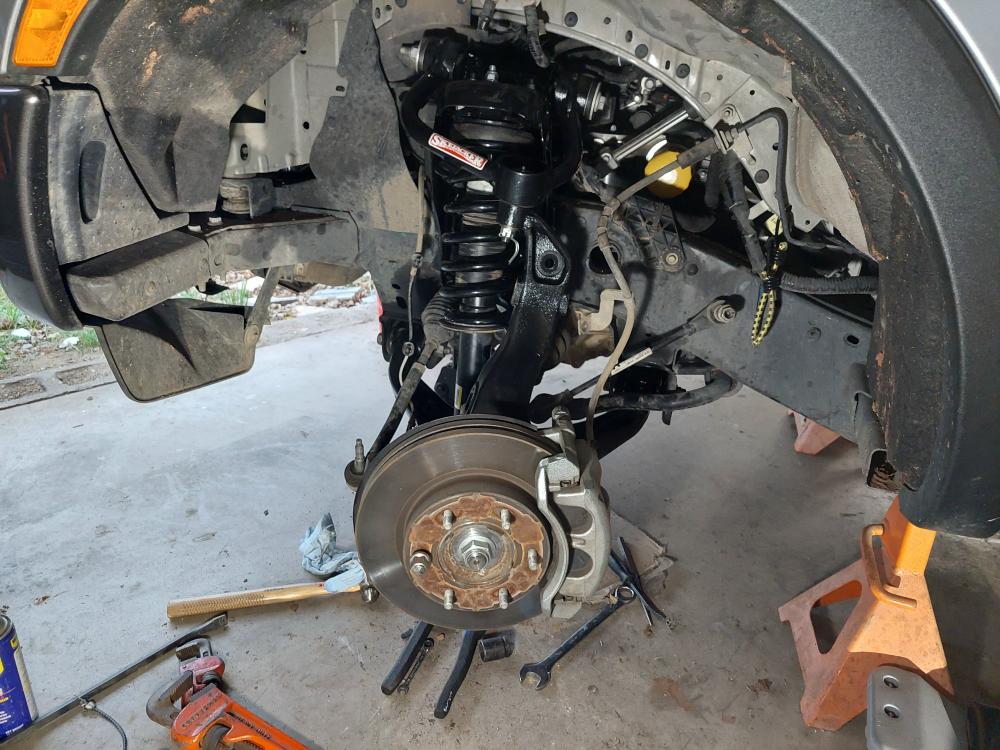
Reinstalled the ABS sensor wire and brake line brackets. Also reinstalled the ABS sensor in the knuckle.
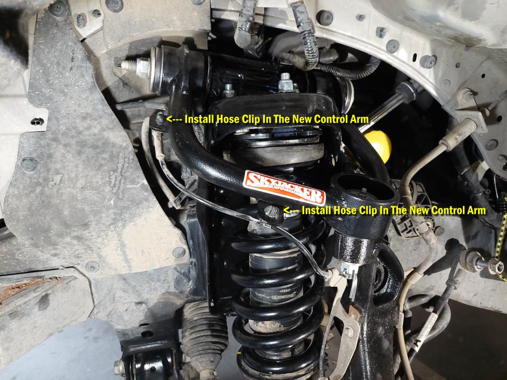
Re-install the hose clips into the new upper control arm.
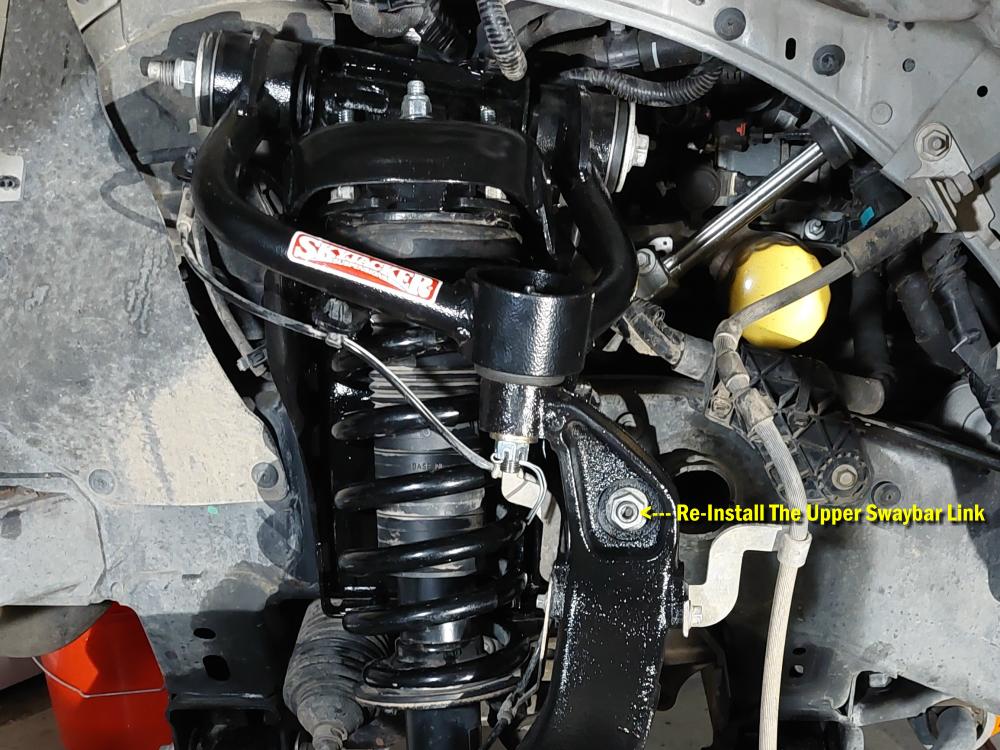
Re-installed the upper sway bar link.
Reinstalled the steering tie rod. Also
Passenger Side Installation:
The passenger side is a repeat of the drivers side.
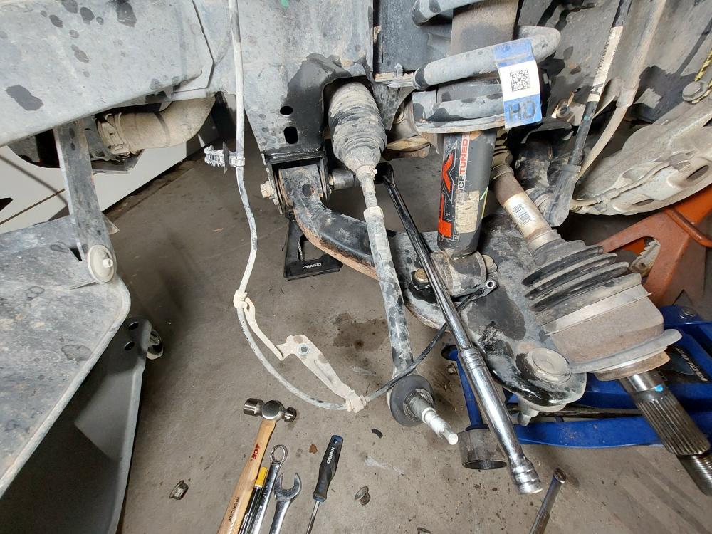
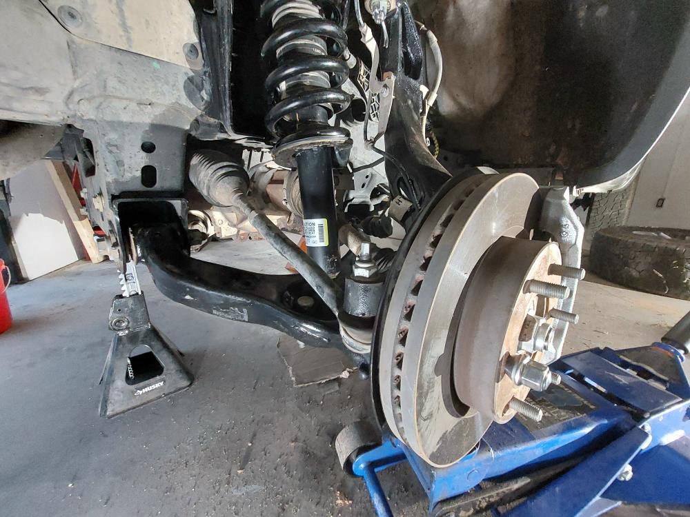
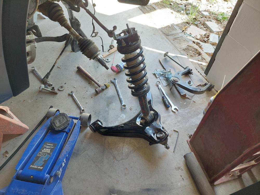
Here you can see where I’m installing the strut with the lower control arm already attached.
Skyjacker 3.5-Inch Lift kit Installation / Front Differential:
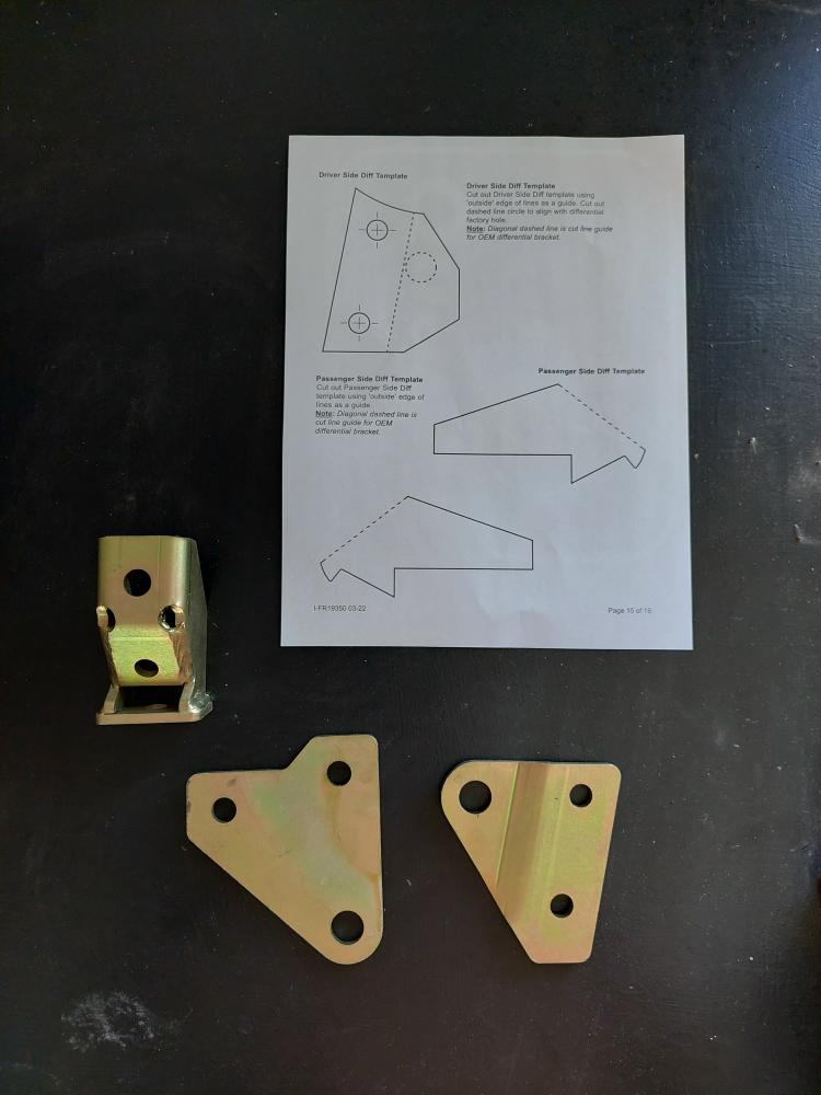
The instructions come with templates to cut out and use as a guide, so you know where to cut the factory front differential mounts.
I placed a floor jack under the differential for this part of the install.
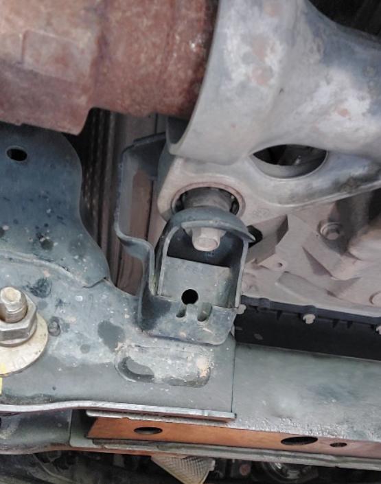
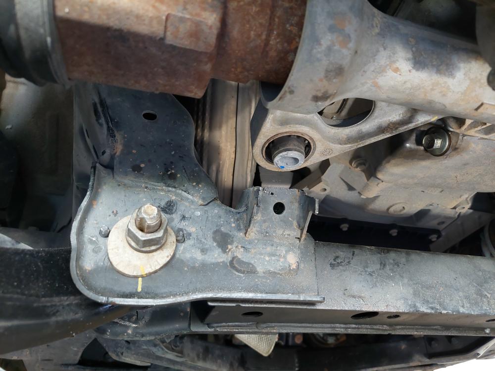
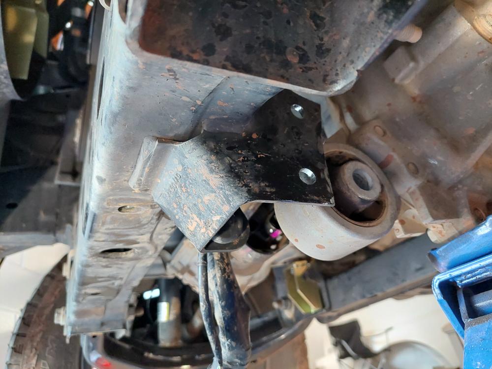
Above you can see the mount on the passenger side of the truck and below you can see where I cut it off.
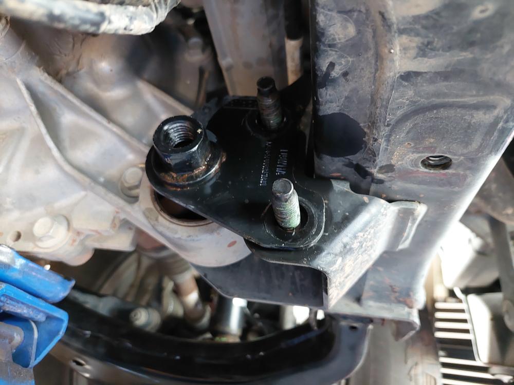
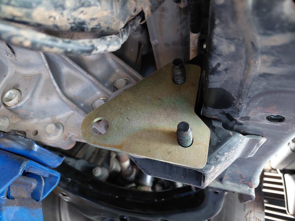
This new 3/16-inch Skyjacker bracket will bolt in its place.
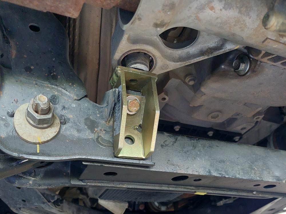
Here’s where it gets interesting. Notice in the photos below from the instructions that this bracket has a nut welded at the top of it. Mine did not. I thought this was something they missed when they welded the bracket, but the Skyjacker photo of the kit components below those photos show the new part without the nut welded to it. Skyjacker supplies a bolt, a dished style washer, and a lock washer, but no bolt. Fortunately, I had a nut to fit it.
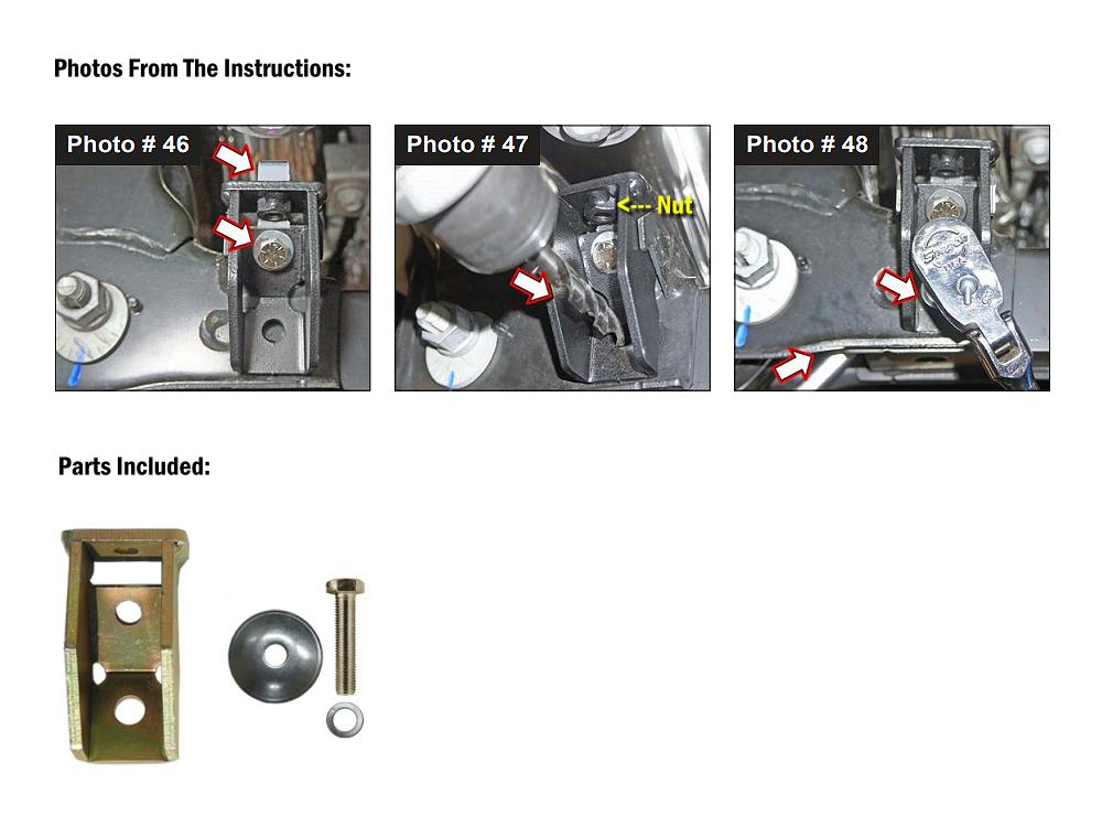
You use a factory hole for the upper bolt, and then drill out the lower bolt hole with a 7/16″ drill bit as shown in the photos above. I did not fully tighten the very top bolt with the nut I supplied until I completed the next step below.
I removed this factory bracket from the (passenger) side of the driver side differential mount.
Removed the long bolt holding the differential in the mount, and then cut this side of the mount using the supplied template.
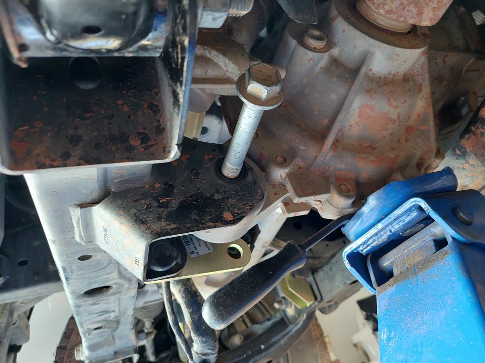
Then fought to drill the two required holes using the marks in the template. This was a pain in the ass. I ended up drilling them from the back (passenger) side. It would have been so much easier if I would have drilled these when the drivers side lower control arm was off.
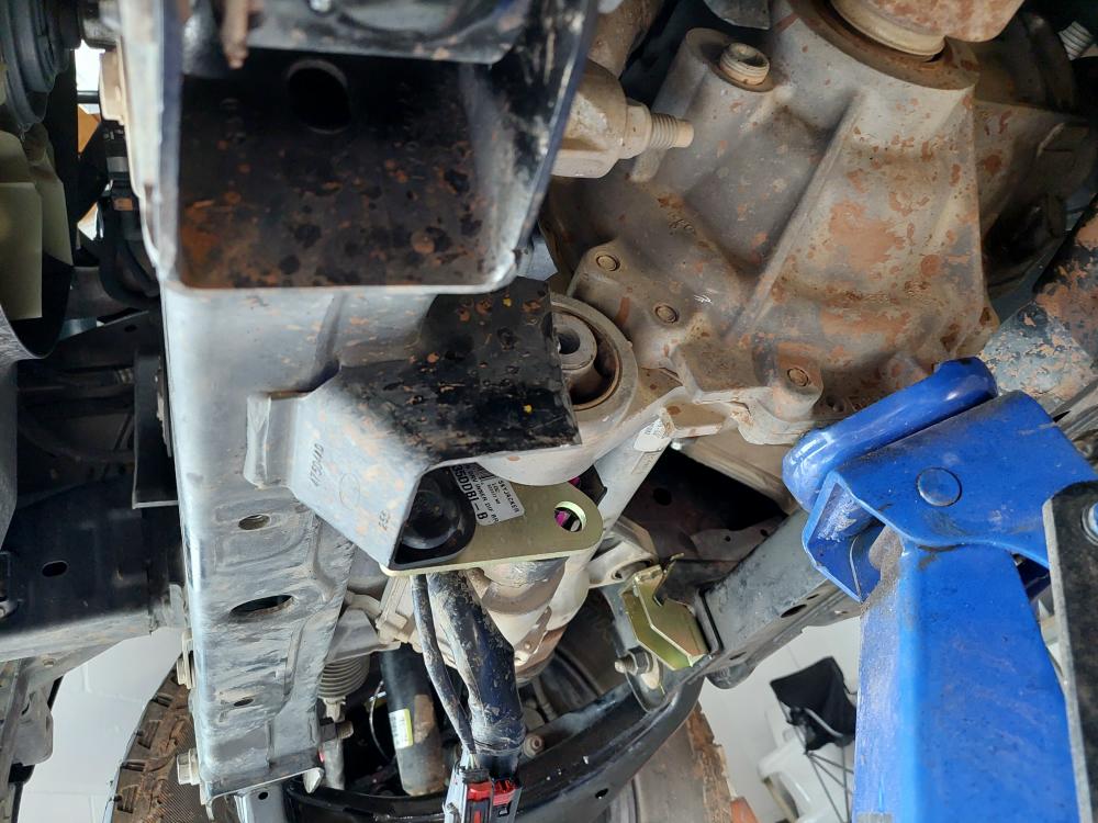
This new bracket bolts on to the passenger side of this mount.
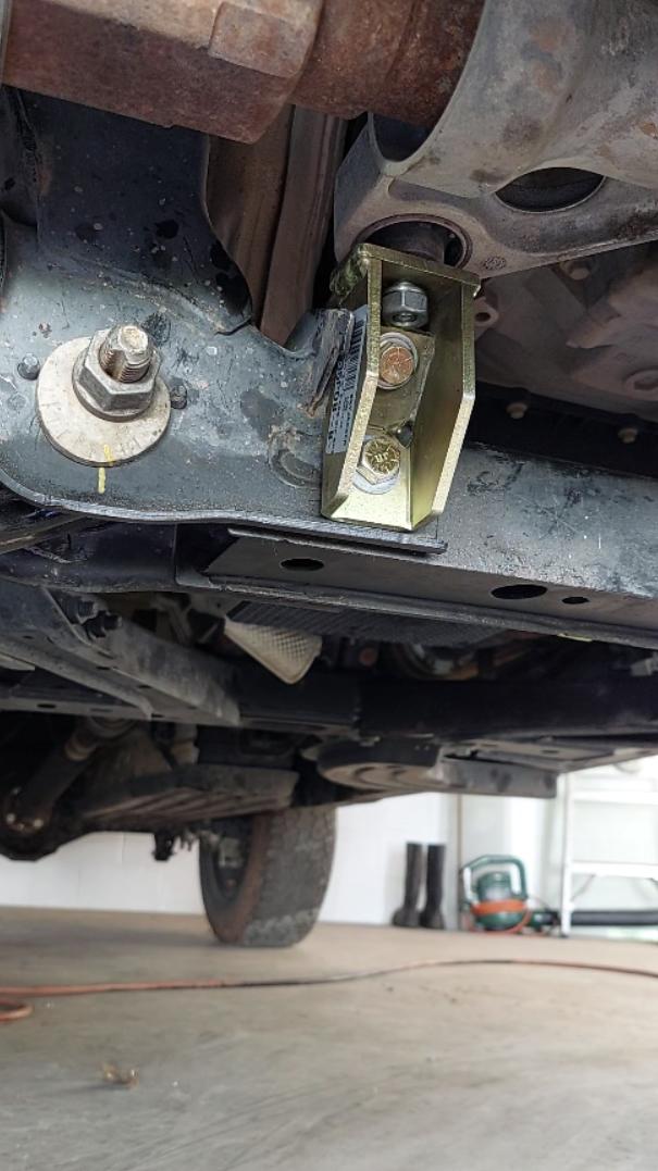
Here’s the new bracket installed on the drivers side of the differential mount after it has been cut.
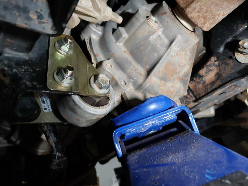
Here’s the other side with everything bolted up.
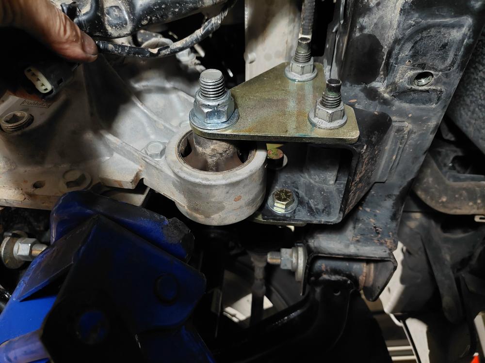
From here I tightened up the top bolt in the first bracket that I installed earlier (the one where I supplied the nut).
With all of this tightened up I put the wheels and tires back on so I could set the truck on the ground and tighten the axle nuts through the removed center caps using a 36mm socket and breaker bar.
Then I reconnected the (3) Electronic Power Assist Steering (EPAS) plugs to the steering assembly.
Then eventually reinstalled the skid plates.
Rear Installation:
The rear lift is pretty easy.
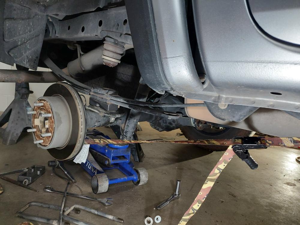
I jacked up the rear of the ranger and set it on jack stands. Since my Ranger has a receiver hitch, I was able to place my large jackstands under the hitch at the frame rails.
With the rear of the truck supported, I jacked up the axle enough to get a rear tire off of the ground, and then removed the tire.
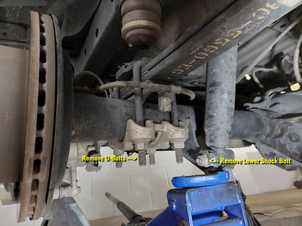
With the tire off, I removed the lower shock bolt. Not sure why. Skyjacker says to swing it out of the way. Maybe they’re concerned you’ll overextend the shock dropping the axle, or that it will keep the axle from dropping away from the spring.
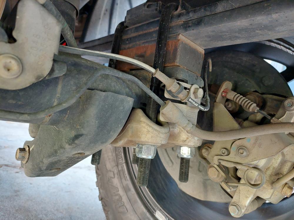
I then removed the (2) U-bolts holding the leaf spring to the axle.
With the U-bolts off, I lowered the jack to allow the axle to drop down from the leaf spring.
I then inserted the new Skyjacker 1.25-inch spacer block between the spring perch and the leaf spring making sure that the pin on the block was in the center hole of the spring perch, and the pin under the leaf spring aligned with the hole in the block.
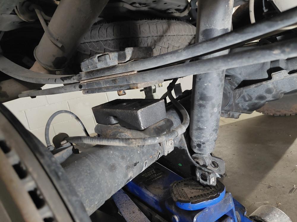
The axle moved back a little when I lowered it, so I attached a ratchet strap to the axle and the frame under the cab and ratcheted the axle forward until the pins all lined up.
With everything lined up I jacked the axle back up until the block was up against the leaf spring.
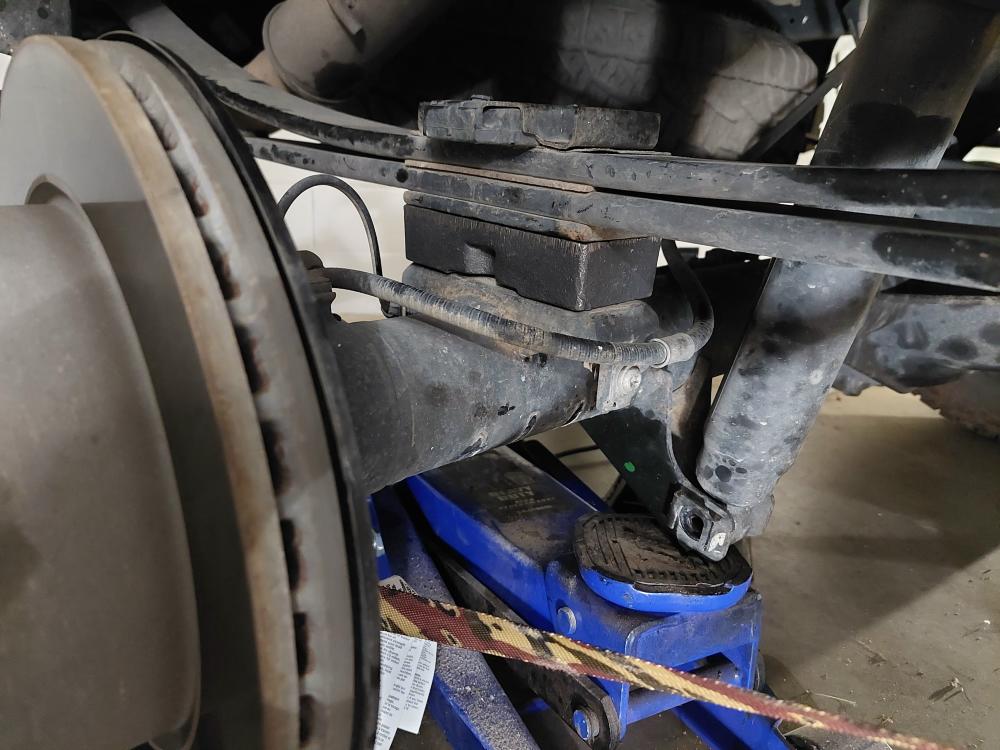
Then installed the new U-bolts and nuts.
Then I repeated this on the other side.
With it all done I reinstalled the lower shock bolt.
Final Steps:
Step 1. Start vehicle. Make sure there are no dash lights pertaining to suspension.
Step 2. Roll vehicle forward and backwards a few feet a couple of times. This will help suspension settle to new ride height.
Step 3. Tighten both Skyjacker replacement upper control arms using an 18mm and a 21mm socket \ wrench to set bushings properly for ride height.
Torque to 122 ft.-lbs.
Step 4. Realign marks on cam bolt positions on lower control arms at frame. Tighten cam bolts on both arms using a 21mm and a 24mm socket \ wrench.
Torque to 165 ft.-lbs.
Note: Final torque will be set by alignment technician.
Final Notes:
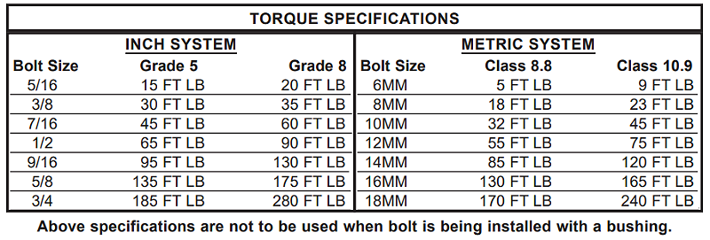
After installation is complete, double check that all nuts & bolts are tight. Refer to following chart for proper torque specifications. (Note: Do not re-tighten nuts & bolts where thread lock compound was used.)
With vehicle placed on ground, cycle steering lock to lock & inspect steering, suspension, brake lines, front & rear drivelines, fuel lines & wiring harnesses for proper operation, tightness & adequate clearance.
You will need to adjust the Ranger’s tire size settings using FORScan.
Have headlights readjusted to proper settings.
Have a qualified alignment center align vehicle to OEM specifications.
After first 100 miles, check all hardware for proper torque & periodically thereafter.
Links:
Video: