
Written and photographed by Evan Vaughan
Process developed by Todd McIntosh
Table of Contents
1. Preface
2. Tool and material requirements
3. Splitting the 1350
4. Making the sector shaft
5. Cutting the 1350
6. Plate fabrication
7. Preparing the 1354
8. Assembly/Installation
9. Driveshaft changes
This document may be freely distributed, provided credit is given to Evan Vaughan and Todd McIntosh.
By proceeding you agree to assume all risks related to building and operating a doubler, including but lot limited to loss of vehicle, accidents, injuries, loss of sleep, broken relationships, and chronic rock crawling.
1. Preface
Why build a doubler?
As tires get larger and larger, more gear reduction is required to provide enough torque at low speed to turn them. Changing differential ratios provides more reduction, but Ranger-based vehicles (RBV) are limited to around 5.13 gears before the pinion gets too small and weak. 5.13s though helpful, provide only limited reduction. If you’re running 3.73s and an M5OD, you’ll go from 35 to 47 in final crawl ratio with 5.13s. A doubler will take you from 35 to 85.
Benefits
Doublers are for trail trucks that need a massive amount of low-end torque and a very low crawl ratio. In addition to excellent reduction, they provide the driver with true 2-wheel low range, as the doubler case can be put in LO and the transfer case in 2 HI.
Basics
This article will describe how to put a Borg Warner (BW) 1350 transfer case in front of an existing BW1354. This is done by splitting the 1350 and keeping only the front half, then cutting the front output housing off of that front half. Then the 1350 half is connected to the 1354 by means of a steel plate between the two. A custom shaft connects the two cases. To compensate for the 6” addition, the front and rear drive shafts must be lengthened and shortened respectively.
Costs
The system can be built for around $400. This includes parts, materials, and tools. Costs will vary for each person and by location. You may already have all the materials laying around in your garage or you may have to buy everything. You might have a buddy with an old Ranger that lets you grab the 1350, or you might have a stuck-up yard that charges a few hundred for a case. Plan on spending at least a couple hundred on the entire project. For me, it cost $300 but I already had all the tools.
Who should build a doubler?
This is a very advanced project. It is harder than rebuilding an engine. One mis-measurement and the entire setup could be shot. This project requires patience and mechanical experience. Plan on at least 7 working days to get it done.
This is only a guide. Each setup may be different. There are so many steps in the project that this would turn into 100+ pages, so each step is not necessarily listed.
2. Tool and Material Requirements
Components
You will need a Borg Warner 1350 manual shift transfer case. You cannot use an electric shift case. Your best bet in finding a manual 1350 is a 1980s Ranger.
You also need an RBV 4×4 output shaft. You only need the end. I went to a junkyard and asked if they had any junk RBV transmissions. Then I had them cut off the shaft with a torch.
Tools
- Normal tools, i.e. socket set, wrenches, c-clamps
- 5” hole saw
- Drill with high-quality metal bits
- Angle grinder with cutting and grinding blades
- 3/8” 16 pitch tap
- If you are going to shorten/lengthen you shafts yourself you’ll need a chopsaw and a welder.
Materials
- 12”x12”x1/2” steel plate
- RTV
- JB Weld
- Brake parts cleaner
- Rags
- 6 – 3/8” bolts, 1.5” long
- 2 – 3/8” bolts, 1/2” long
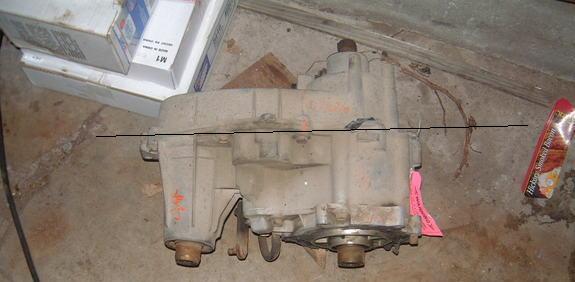
3. Splitting the 1350
This is one of the easiest parts of the job.
Remove the center bolts holding the two halves of the case and pull it apart.
You can then remove the bolts holding the front plate and pull that off; the planetary set will come out with it.

The rear housing with all the components are junk.
4. Making the sector shaft
This is a part where you’ll be heading to the local machine shop, unless you have an arbor press and a metal lathe. The cost for this should be between $50 and $100.
Take the sector shaft (the main shaft inside the case) and your 4×4 output.
Tell them what the application is. Tell them the shaft needs to be build to handle the most torque possible. They need to first cut down the sector shaft, then bore it out. Then they need to lathe down the 4×4 output and press the two together. Finally, the two need to be welded together. You’ll start with this:

4×4 output top, sector shaft bottom. Remove that little ATF pump and discard it.
And you’ll end up with this;

As for the length, you cut the sector shaft off at the gear, then the 4×4 output goes in with the splines ending right where the sector shaft begins.
5. Cutting the case

You’ll have the front housing with the planetary set removed, after The next step is to cut the front output housing off. As looking at the above picture, you want to keep the bottom hole and cut through the top hole. Below is what you should end up with.

Throw away the housing on the right. You now officially have a doubler housing. There is a ½” gap at the end of the case, this can be filled in with some of the ½’ plate bolted in and sealed with JB Weld.

Drill and tap drain/fill holes in the top and bottom of the case.
6. Plate Fabrication
Line up the doubler housing on the plate. Make a center mark on the plate through the input hole and get to work with the 5” hole saw. It will take at least 20 minutes to cut through the plate.

Once the hole is cut you can line the case back up on the plate. Drill out and tap the two most outer boss holes into the plate. These will thread into the plate. The remaining case boss holes around the 5” hole will thread into the case from the opposite side.

You can clean out the case and reinstall the front plate. Above: the first of the outer two holes has been drilled and tapped into the plate. The bolt is threaded in on the bottom right.
Next, drill 7/16” holes for bolts to thread into the case from the opposite side as shown below.

Finally, place the doubler case on the plate and cut it out.

You’ll need to cut down the shaft that the shift fork rides on and grind a recessed hole in the plate for it to sit.
7. Preparing the 1354
The 1354 front plate has to be ground down in three places in order to fit over the bolt heads going into the 1350. You’ll need to remove the 1354 front plate and see what needs to be ground down.
Once you get the plate seated you can drill the holes into the steel plate and tap them. You may wish to clock up the transfer case a little if you think you’ll have drive shaft clearance issues with the tranny crossmember. One bolt goes through the plate and threads into the 1354, the remaining go from the 1354 front plate into the steel plate. These are the 1.5” 3/16 bolts you purchased. You’ll have to drill out the threads in the bosses, as the stock setup has bolts thread into the 1354 plate from the tranny.
Since the 1354 breather tube output is now right in front of the plate, you’ll need to cut down the existing fitting in order to be able to fit a hose over it. You can also find and thread in a 90 degree fitting.

Additionally some minor grinding may need to be done on the actual case for bolt head clearance. Clearance issues are huge in this project. Basically, grind where the need arises.
8. Assembly/Installation
It is recommended that you do a trial assembly to make sure everything fits before RTV sealing it.
Order:
1. Begin with both front plates removed from the cases
2. Bolt the doubler case onto the plate
3. Bolt the transfer case plate onto the plate, with the plate-to-case bolts in place
4. Assemble the internals in the doubler case
5. Install the doubler case front plate, check to make sure the case shifts ok
6. Connect the 1354 to its front plate
7. Fill the doubler case with ATF, the t-case can be filled after installation


9. Driveshaft Changes
Your front shaft will need to be lengthened and the rear shortened, both by about 6”.
You can have a shop do this or do it yourself. You’ll need a chopsaw and a welder if you want to do it yourself.
Cut the front shaft right in the middle. Find a piece of pipe that has ¼” thick walls and is the right diameter to fit in or over the shaft, and weld it on.

For the rear: Grind off the weld where the male splines for the slip yoke come out of the driveshaft. Cut the necessary amount off the shaft, then hammer out the splined cup. Re-weld it to the shorter shaft.
WARNING – DO NOT put the doubler case in LO and the transfer case in HI. Also, you should have the newly created splined shaft heated prior to welding and then cooled slowly to prevent cracking. ~ Jim Oaks.