
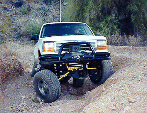
Over the years I’ve came across some interesting rigs. Some in magazines, some on the internet and some on the trails. One of the most famous rigs to sport a Dana 35 TTB front suspension wasn’t a Ranger, but a Ford Explorer. In 1997, Lee and Gloria Zimmerman’s 1993 Ford Explorer was hitting the pages of magazines and showing up on the internet. I still have the magazine stories of it from the November 1997 4X4 Performance Magazine and March 1998 Four Wheeler Magazine. Showing up on the net is nothing, gracing the pages of a magazine is something to be proud of.
It wasn’t so much that this 4.0L Explorer had a Vortech supercharger and 4.56 gears, it was the 19-inches of useable, reliable wheel travel from the Ford TTB suspension!
How They Did It:
Axle Beams, Brackets & Coil Towers:

“I started with a truck that had a badly damaged Superlift 5.5-inch lift. All the drop brackets were bent and/or cracked. I made some attempts at reinforcing these parts with only marginal results. Replacing the lift with the same components, or similar was not an option. I checked into how the off-road race trucks were setting up their front suspensions. Their solution was to cut and turn the I-Beams for 4 inches of lift, and run stock pivot point brackets.
I pulled the explorer into the garage, and raised it up on jackstands, making sure the truck was level from front to rear and side to side. Once accomplished, I removed the front suspension from the truck.
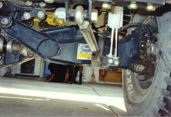
First, the shock mounts were cut off of the spring tower. This makes room for dual shock brackets to be built and installed.
The modified tower was then re-attached to the frame 1-1/2 inches lower than it’s stock location by drilling new mounting holes in the sides and installing a spacer between the bottom of the frame and the spring tower.
Next, the right I beam pivot bracket was bolted to it’s stock location on the engine crossmember. A plumb line was hung so that it passes over the center of the I-Beam mounting hole. The bracket was moved 3 inches straight down, and reattached to the crossmember by a short drop bracket, similar to the way most lift kits do. Later, a brace will be run from the I beam mounting bolt, back to the new radius arm crossmember.
Now, the left I-beam’s factory pivot bracket is bolted to the right frame rail. This requires temporary removal of the modified spring tower. A plumb line is used as previously mentioned, and a jig is built that positions a 9/16 in. hole, 3 inches lower than the factory bracket. The flange with the hole on the jig should be positioned slightly to the rear of the truck, from the rear edge of the factory bracket. A bolt will run through the jig and hold the new pivot point in it’s proper location, as it is built.
The jig must be designed so that it does not interfere with bolting the spring tower on the frame.
The new drop bracket must be built VERY heavy duty, as this is the most likely one to bend.
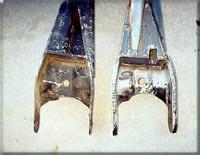
The right hand I-beam is the easiest, so do it first. Remove the radius arm. A jig is built that mounts the arm by the bottom radius arm mounting bolt, and the two sway bar mounting bolts. Remove the sway bar mounting bracket. The bushing is removed from the eye, and a plug is made out of wood.
The wooden plug is used to replace the bushing, as the center hole on a bushing is usually off-center or twisted. This also allows the metal face of the eye to mate tightly with the jig.
To ensure proper alignment with the arm bolted to the jig (with the 3 bolts described earlier), build the jig to extend out to the pivot point.
Mark the center of the pivot point on this part of the jig.
Measure 4 inches straight up, and drill a hole to mount the pivot point.
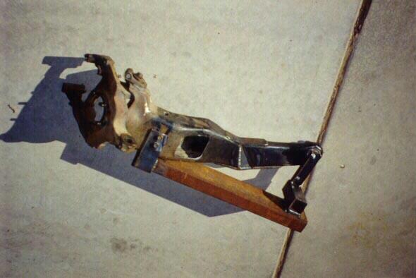
After the I-Beam has been cut, reinstall both halves in the jig and use the jig to position both halves for re-assemble.
“The Left hand I-Beam jig is built in the same manner, except the mount for the radius arm hole has to be spaced up on the end, due to the differential housing. The jig uses the lower differential mounting hole to mount the beam. All other steps remain the same as stated above”.
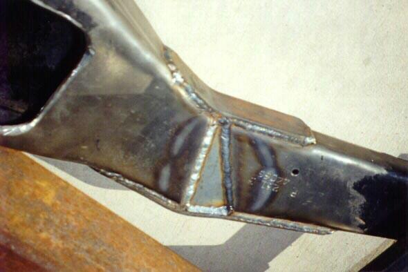
Use 3/16 steel to make the patches to reassemble the beams.
Plates are added on the front and in the rear.
Make one larger than the other so that the welds are spaced out.
The top and bottom flanges are also plated and welded back together.
During this process, I chose to add an extra plate to the bottom of the differential housing to act as a skid plate.
A new crossmember is added to the frame just ahead of the transmission crossmember.
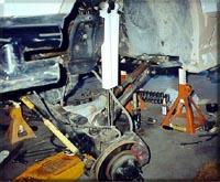
The radius arms are installed on the I beams, and then the I beams are installed onto the truck.
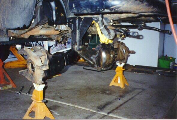
Use jack stands to hold the ends of the I-beams at the desired ride height.
Ratcheting tie down straps are used to position the I-beams front to rear, adjusting how the tire fits in the wheel well. (I positioned the tires 3/4″ farther forward to prevent rubbing at the rear of the wheel well during full compression. Measurements were taken on a stock explorer by measuring from the door joint to a plumb line taped to the fender).
Jacks are used under the ends of the radius arms to position them for the desired caster angle. Again, measurements were taken from a stock Explorer. I placed a tri-square vertically on the flat surface of the rear of the I-beam, close to the steering knuckle. Washers were placed under the bottom edge of the square until the level read level.
Jacks were used to raise or lower the radius arm ends until the square showed level with the same stack of washers under the bottom.
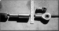
Then 1-1/4″ OD. 3/4″ ID DOM tubing with a bolt welded in one end, mounting a 3/4″ Heim joint was installed through the cut in the radius arm, extending back to the new crossmember.
The Heim joint mounts are temporarily attached to the crossmember, then the tubing was welded and heavily gusseted inside the radius arm.
Front Coils:
Springing the Explorer depends on its usage. For the majority of situations the Zimmermann’s encounter, National coils measuring 22″ in free length and 325 lbs. per inch are employed. The lighter rate and longer free length allow more droop from the TTB’s modified arms, and keep the front end in contact with terra firma. When the game plan call’s for fun in the dunes however, the Zimmermann’s swap in a heavier set of Superlift coils measuring 19″ free length, and rated at 450 lbs. per inch.
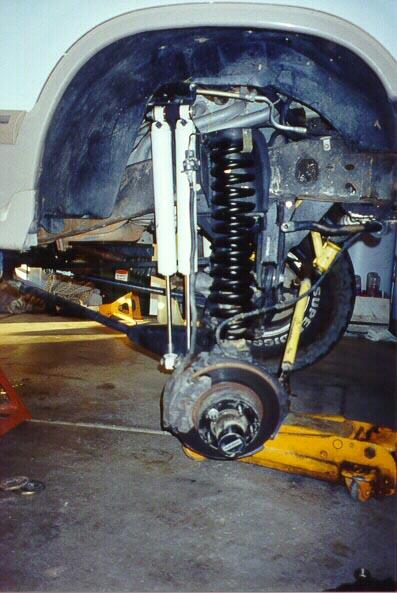
Shocks & Steering:
2 Rancho 9000 series (9012) shocks per wheel are employed to control the big 33 in. Yokohamas through the suspensions 19 inches of articulation. With an extended length of 33.10 in. and a collapsed length of 18.9 in., the 9012’s are the longest shock in Rancho’s “standard” arsenal (The “Lightning Rod” & RS5000 Take Apart” Series race shocks come in longer lengths). Paired up, the 9012’s adjustable settings result in 25 useable settings per side.
With the “Inverted “Y” steering linkage placed carefully in the trash, The Zimmermann’s employed Superlift’s new “SuperRunner” steering linkage to handle the Explorers steering chores. The SuperRunner linkage employs a drag link and independent rods for each wheel. Mounted from the steering knuckles to the (near) center of the drag link, the result is minimal bump steer over a wide range of suspension travel.
Problems Encountered:
As modified we have a few minor catches. The slip joint in the right hand axle shaft compresses so far that it blows the cap out of the end of the female splines. We cut the c-clip groove off of the axle shaft to move the shaft further into the carrier. We then built an external retainer. We are looking now at possibly making a domed cap or enclosing the entire u-joint assembly in a CV type boot. Another headache, if your steering stops are slightly worn, you will need to weld them up. Otherwise you will bind the yokes for the axle u-joint in the right hand steering knuckle.
As far as the limitations of our system go. We could get a marginal amount of pivot travel out of the heim joints if we messed with the side bushings. It wouldn’t be much more, but it could be done. The end that meets the ball of the heim joint would have to be machined to a taper on a lathe. As far as the axle goes, any IFS is going to reach its limitations at some point. We could probably push it a bit more, but frankly we are pretty happy where we are. It would be a lot of effort for just a little gain, and it may sacrifice reliability, which is always a top concern.
Radius Arm Update:
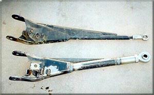
After leading Woodpecker at the AZ State Assoc Jamboree in Oct 97, we built new radius arms. The reason, we bent the old ones, and the crossmember.
The new radius arms are built with 2″ tubing with 1/8″ wall thickness (schedule 160). They are connected to the stock sections of the arms in the same manner as before, but more reinforcing is used. We also double plated the mounting area of the arms. We are now using 1″ heim joints with a load rating of 24,000 pounds (they weigh 2 1/2 pounds each). The ends of the arms where the heim joints connect are made out of solid stock.
We turned them down on the lathe so that they could be press fit into the tubing (a 12 ton press was maxed out doing this). Lee radiused both the tubing and the solid stock to accept a thick bead of weld. He then turned out the other end, and tapped it to receive the heim joints. We then built a new cross member out of square tubing for more strength.
For those people who may be interested in doing something like this, there is one thing they need to know. The upper bolt for the passenger side radius arm needs to be spaced up 1/4″ and the end needs to be relieved 1/8″. This is due to the amount of vertical axle movement from the travel. If you do not do this the axle will bind and the washer that goes on the end of the stub shaft to retain the axle in the spindle will get mutilated and pulled in.
When this happens, the axle falls out of the spindle. Not good. Other than that, there have been no reliability problems with this modification to the front, and that is easily solved. We have now run many thousands of miles on the truck, and have done the hardest trails in AZ with ease. The truck will even make believers out of the Jeep crowd.”
What about the rest of the truck?
Here’s a few details about other modifications to the truck:
Front Axle:
The differential is a Lockright with 4.56 gears. We made a c-clip eliminator for the stub shaft to make assembly of the lockright as easy as possible. Sway bar disconnects were fabricated for both sides of the swaybar. A holder was build off of the frame to keep the sway bar out of the way. The Superlift Superrunner steering is used to eliminate bump steer. When the radius arms were built, we built more caster angle into the front end. This makes the truck much more stable on the highway.
Rear Suspension:
New spring pads were welded on top of the axle. We cut the eyes off of the stock Explorer spring pack and put the main leaf from the Ranger on top (gave us more than 2″ more drop travel and more up travel for $65). New lower shock mounts were built off of the spring pads (on top of the axle) to get the shocks out of harms way. A crossmember was built where the old spare tire used to be, for the top mount on the shocks. This was put as high as possible. The dual Ranch 9000’s are now at an extreme angle to give as much travel as possible. The rear swaybar also has disconnects on both sides. There is a Detroit c-clip locker w/ 4.56 gears.
Engine:
73mm mass air, 63mm throttle body, 1 3/8″ Pacesetter headers (jet-hot coated), 2 1/2″ exhaust with Dynomax muffler. The cat and the muffler are ridged mounted with flex pipe between them. The exhaust is mounted as high as humanly possible. There is also a Superchip.