• Welcome Visitor! Please take a few seconds and Register for our forum. Even if you don't want to post, you can still 'Like' and react to posts.

2.3L ICM Problem


2.3sandrail

Member
Joined
Feb 22, 2022
Messages
11
City
tucson az
Vehicle Year
88
Transmission
Manual
Hello so i am building a sand rail with a 2.3 from a 88 tbird.. so my problem is with the Darkgreen / Yellow wire is not passing a continuity check... it is # 4 pin on the 60 pin connector.. i will get continuity from the 60 pin connector to the resistor and nothing pass the resistor... i am looking for options. can i jumper the resister? or what is the value of the resister.. and can you even continuity check a wire with a resistor on it.... i would like to get the rail going..... thanks for your help
 
This diagram doesn't show a resistor. You are not talking about a round silver can that is called a capacitor are you?
 

Attachments

This diagram doesn't show a resistor. You are not talking about a round silver can that is called a capacitor are you?

This is what I am talking about.... looking at the pic I am getting continuity to the right side of it but not to the left
 

Attachments

  • 20220224_163259.jpg
    20220224_163259.jpg
    93.1 KB · Views: 164
  • 20220224_163338.jpg
    20220224_163338.jpg
    110.4 KB · Views: 159
  • 20220224_163401.jpg
    20220224_163401.jpg
    141 KB · Views: 157
Welcome to the forum

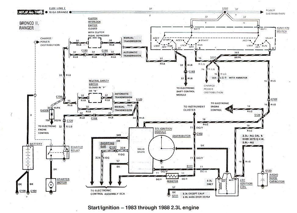
Shown at the bottom of this diagram: https://www.therangerstation.com/tech_library/EDiagrams/files/Diagrams_StartIgnition83to88_2_3.JPG

Its on the "tach" signal wire, AKA IDM signal, but on the connection to computer for RPM, the green/yellow wire also runs to the Cluster for Tachometer use, in 1988, tan wire in later years

So just to understand, there is no continuity THRU the resistor, or no continuity from resistor to pin 4 on the EEC(computer)?

It is a 22K ohm resistor and needs the resistor for the computer pin 4 hookup, so no don't bypass it
But IDM is ignition diagnostic monitor, so its just a monitor circuit not used for start up or running the engine, i.e. engine will run just fine without a tachometer, it will throw a code with no IDM signal, but thats all
If you have a no start its not because this resistor or wire is bad
You can use a 1/2watt 22k resistor from "radio shack" type store to replace it

Do 50/50 test
Spray fuel into the engine and try to start it
If it starts and dies then you have a fuel delivery issue
If it doesn't start then its a spark issue, but not IDM wire
50/50 instant results on where to look

TFI module on distributor is autonomous, doesn't need the computer to start spark or keep engine running
Computer is for fuel injection, and "load" spark advance
On older distributors there was Vacuum Spark Advance, this was "load advance", when you "stepped on the gas" vacuum would drop and spark timing would change
With the TFI system, the SPOUT signal from the computer is Load Advance, because computer has the Throttle Sensor and MAP sensor it can "tell" TFI when and how much to change spark timing based on engine load
But SPOUT is not needed for start up or running, just for running better, lol

So treat the spark system and fuel delivery systems as totally separate entities
 
Last edited:
Just to ease your mind and to check the resistor more accurately, take your meter off continuity and put it in ohms mode. Some meters have just one spot for ohms and are auto ranging. Some meters have different ohm ranges. Ron said the resistor is 22,000 ohms or thereabouts. If your meter has ohm ranges, make sure you select ohms times 1000. Your reading will be around 22 for 22 thousand. Some meters can give you a out of range error if you are not in the right range.
 
Hi so i am 99% i am not getting a spark.. i am getting power to the coil tested it with old school test light flicker on both sides when cranking
 
Hi so i am 99% i am not getting a spark.. i am getting power to the coil tested it with old school test light flicker on both sides when cranking
With the test light clipped to a good ground, you should get a solid light on the + side of the coil, and a flicker on the negative side of the coil when cranking. Flicker on both sides is not correct.
 

Sponsored Ad


Sponsored Ad

TRS Events

Member & Vendor Upgrades

For a small yearly donation, you can support this forum and receive a 'Supporting Member' banner, or become a 'Supporting Vendor' and promote your products here. Click the banner to find out how.

Recently Featured

Want to see your truck here? Share your photos and details in the forum.

Ranger Adventure Video

TRS Merchandise

Follow TRS On Instagram

TRS Sponsors


Sponsored Ad


Sponsored Ad


Amazon Deals

Sponsored Ad

Back
Top