• Welcome Visitor! Please take a few seconds and Register for our forum. Even if you don't want to post, you can still 'Like' and react to posts.

Vacuum Hookup + Reservoir Mystery


eightynine4x4

Active Member
Joined
Oct 15, 2020
Messages
673
Reaction score
178
Points
43
Location
New York
Vehicle Year
1989
Make / Model
Ford Ranger
Engine Type
2.9 V6
Transmission
Automatic
2WD / 4WD
4WD
Total Lift
2.5" Suspension
Tire Size
31 x 10.5 x 15
Hey folks,

So i've just finished a lot of other work and still have some persistent idle problems, somewhat wild ones sometimes, and am trying to finally eliminate vacuum from the list of possible causes.
I've started doing some tests of vacuum connections and lines and did find very minor leaks and replaced parts, and eventually got to the reservoir section of hoses which is one section i don't understand and i also got some readings i wasn't expecting....

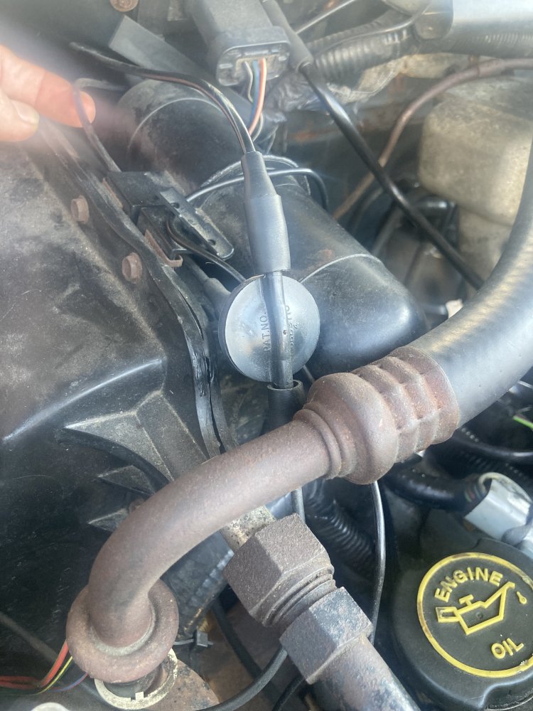
The way my reservoir "section" is currently hooked up.... there's a thin hose coming from the plenum multi connector vacuum point thing on drivers side (which is fed by the master vacuum unit), and this thin hose goes all the way over to the passenger side and hits the center/bottom connection of a T shaped flying saucer device which is pictured below. Then one upper "side" feeds the reservoir, and the other upper "side" feeds a thin hose that goes down to the vacuum motor underneath air intake which controls the warmup flap thing. Anyways, back to the T-shaped flying saucer.... I take this to be some kind of check valve, but i've not found any explanation as to how the design of this particular check valve functions. I also haven't found a single check valve on the interwebs for a ford ranger that is designed like this one, which is surprising. So, i can't confirm that it's hooked up correctly. It has 3889710 stamped on it. Is its center/bottom supposed to be fed from the master vacuum? And the two sides to the above mentioned destinations? In the picture you can see my finger holding the line that feeds the center of it, and this is the line coming from master vacuum. You can also sorta see the line coming from the side of the flying saucer that feeds the back of the reservoir, and you can see the line from other side that goes down into the engine bay to the vacuum motor under air intake.

Now... I decided to at least check for vacuum on these lines, and also decided to check the reservoir itself. I can only get the reservoir to hold say 5-7 HG for a split second and then it quickly drains. Is that supposed to be the case? Or is mine faulty? I thought this reservoir unit is intended to hold vacuum so that it's available when it's needed during acceleration, or so i've read somewhere. Does that mean it's supposed to be more or less immediately "filled" with like 18-21 HG of vacuum once the engine is running, and then basically stay at that level until something chooses to drain it? I guess that check valve is supposed to drain it on cue and send it to the... correct place? Back to the plenum?

I truly don't understand how it works and the diagrams I've found don't draw up the connections thoroughly. Any help would be greatly appreciated!!!

thanks!

tempImage66X8en.jpg


franklin2

Well-Known Member
Joined
Dec 24, 2019
Messages
3,422
Reaction score
1,758
Points
113
Location
Virginia
Vehicle Year
1984
Make / Model
Bronco II
Transmission
Manual
The flying saucer thing is a check valve. It lets flow go from the reservoir to the plenum, but does not let flow go from the plenum to the reservoir. Since this is vacuum, you have to think backwards. The air flows from the reservoir to the engine as the engine is sucking the reservoir down to a vacuum.

When the engine starts pulling a hill, the vacuum in the engine goes to zero. So the air or zero vacuum would start flowing from the engine to the reservoir if the check was not there. This whole system is to stabilize the vacuum for the vacuum operation of the HVAC and other components. For example if you did not have the reservoir and the check, when you started pulling a hill the air from the vents would switch to defrost. As you get over the hill and close the throttle, the vacuum would come back and the air would switch back from the defrost to whatever setting you had it in before.

If you want to check the operation of the check, you should be able to suck through it one way, but not the other.
 

eightynine4x4

Active Member
Joined
Oct 15, 2020
Messages
673
Reaction score
178
Points
43
Location
New York
Vehicle Year
1989
Make / Model
Ford Ranger
Engine Type
2.9 V6
Transmission
Automatic
2WD / 4WD
4WD
Total Lift
2.5" Suspension
Tire Size
31 x 10.5 x 15
The flying saucer thing is a check valve. It lets flow go from the reservoir to the plenum, but does not let flow go from the plenum to the reservoir. Since this is vacuum, you have to think backwards. The air flows from the reservoir to the engine as the engine is sucking the reservoir down to a vacuum.

When the engine starts pulling a hill, the vacuum in the engine goes to zero. So the air or zero vacuum would start flowing from the engine to the reservoir if the check was not there. This whole system is to stabilize the vacuum for the vacuum operation of the HVAC and other components. For example if you did not have the reservoir and the check, when you started pulling a hill the air from the vents would switch to defrost. As you get over the hill and close the throttle, the vacuum would come back and the air would switch back from the defrost to whatever setting you had it in before.

If you want to check the operation of the check, you should be able to suck through it one way, but not the other.
Thanks! I understand this, but don’t quite get how the components and hookups are meant to be in my truck. There are 3 connections to the check valve. Does it sound like mine are connected properly? It goes from plenum to center of check, then one side of check goes to reservoir and other side of check goes down to the little vac motor (for intake hot air during warmup).
And I suppose most importantly… should the reservoir be able to hold vacuum when tested on its own? Like when I disconnect it from the vacuum system / check, and hook up a Mityvac, it doesn’t hold anything. I don’t see how a fully leaking reservoir would function any different than just leaving that half of check valve wide open to air at that point, right?
 

franklin2

Well-Known Member
Joined
Dec 24, 2019
Messages
3,422
Reaction score
1,758
Points
113
Location
Virginia
Vehicle Year
1984
Make / Model
Bronco II
Transmission
Manual
Take the reservoir out and see if it is cracked anywhere. If your mighty-vac will hold vacuum, the reservoir should also. But there is no check in the reservoir itself, air flows to and from the reservoir as it stores and then supplies vacuum continuously as you are driving.

If your mighty-vac is leaking down, then you could rig the check valve in the line before it enters the reservoir, so the check will hold the vacuum in the reservoir.
 

eightynine4x4

Active Member
Joined
Oct 15, 2020
Messages
673
Reaction score
178
Points
43
Location
New York
Vehicle Year
1989
Make / Model
Ford Ranger
Engine Type
2.9 V6
Transmission
Automatic
2WD / 4WD
4WD
Total Lift
2.5" Suspension
Tire Size
31 x 10.5 x 15
Take the reservoir out and see if it is cracked anywhere. If your mighty-vac will hold vacuum, the reservoir should also. But there is no check in the reservoir itself, air flows to and from the reservoir as it stores and then supplies vacuum continuously as you are driving.

If your mighty-vac is leaking down, then you could rig the check valve in the line before it enters the reservoir, so the check will hold the vacuum in the reservoir.
The mighty vac is working fine, and is holding vacuum on other lines and components. The reservoir is the only thing that’s not holding vacuum, so I guess I have to conclude the reservoir is busted.

If it’s hooked up the way it has been, I wonder how a busted/leaking reservoir would impact the operation of the vacuum system overall.

But I’ve also got to figure out how exactly this is supposed to be hooked up…
 

eightynine4x4

Active Member
Joined
Oct 15, 2020
Messages
673
Reaction score
178
Points
43
Location
New York
Vehicle Year
1989
Make / Model
Ford Ranger
Engine Type
2.9 V6
Transmission
Automatic
2WD / 4WD
4WD
Total Lift
2.5" Suspension
Tire Size
31 x 10.5 x 15
Was able to detach the connector from the reservoir itself and hook up all new ones to MightyVac now so it’s a true test of the reservoir itself. Previously there was one old connector on there still.
The reservoir very slowly builds vacuum, which makes sense because it’s large. It takes like 30-40 pumps to get it to 21 HG. But now it holds rock solid.
So the leaky reservoir was really just a leaky main connector to it. Will replace and reinstall accordingly.

I’ve still got to figure out exactly how this check valve works, with its 3 connectors… and then hook it all up properly.
 

franklin2

Well-Known Member
Joined
Dec 24, 2019
Messages
3,422
Reaction score
1,758
Points
113
Location
Virginia
Vehicle Year
1984
Make / Model
Bronco II
Transmission
Manual
I re-read your post a little more closely, and found the vacuum diagram for a 1989 2.9 v6. What you have there is not in the diagram and doesn't sound correct if that is the year you are working on. I will attach the diagram I found. There is no 3 port valve thing in the diagram for the heat door on the air snorkel.

"Man" is manifold vacuum.

"AC/BIMET" is Air cleaner Bi-metal and this is the temp sensor located in the air tract somewhere. This temp sensor is what regulates the vacuum to the "A/CL DV" which is the Air Cleaner diverter.
 

Attachments

franklin2

Well-Known Member
Joined
Dec 24, 2019
Messages
3,422
Reaction score
1,758
Points
113
Location
Virginia
Vehicle Year
1984
Make / Model
Bronco II
Transmission
Manual
P.S. I looked at the picture a little more, that stuff in the picture may have to do with the HVAC system vacuum, which is not shown the the diagram I attached. But it certainly sounds like things are a little mixed up under the hood. I don't have a HVAC vacuum diagram.
 

eightynine4x4

Active Member
Joined
Oct 15, 2020
Messages
673
Reaction score
178
Points
43
Location
New York
Vehicle Year
1989
Make / Model
Ford Ranger
Engine Type
2.9 V6
Transmission
Automatic
2WD / 4WD
4WD
Total Lift
2.5" Suspension
Tire Size
31 x 10.5 x 15
Yeah, attached below is the diagram on my actual truck which matches the one you found.
And yeah it’s been a little weird to figure out what this check valve situation is, since it’s not at all represented in the diagram. There also is zero HVAC connection to my vacuum stuff. But, that’s not drawn on diagram anyways.
So the only thing I can come up with is that the sole purpose of the check valve is to retain vacuum for the air diveter since it’s a vacuum motor, so that it can still run when there’s no vacuum in engine. That’s the way it seems to be hooked up. But I don’t see what the purpose of that is. So it’s a mystery still.

Currently I have the whole diverter situation blocked off… there is a line from plenum that goes to the bimetal, which I plugged at the plenum. There is also a line that goes from plenum over to the check valve in question, and I plugged that spot at plenum too. I am rolling like that for the time being. I’ll worry about the warmup air temp at some layer date when I have more of this figured out!
66BE4E16-9D01-499C-9181-6751D0D9A893.jpeg
 

Sponsored Ad


Sponsored Ad

Staff online

Member & Vendor Upgrades

For a small yearly donation, you can support this forum and receive a 'Supporting Member' banner, or become a 'Supporting Vendor' and promote your products here. Click the banner to find out how.

Truck of The Month


Shran
April Truck of The Month

Recently Featured

Want to see your truck here? Share your photos and details in the forum.

Follow TRS On Instagram

TRS Events

25th Anniversary Sponsors

Check Out The TRS Store


Sponsored Ad


Sponsored Ad

Sponsored Ad


Amazon Deals

Top