• Welcome Visitor! Please take a few seconds and Register for our forum. Even if you don't want to post, you can still 'Like' and react to posts.

Thinking of building a press brake. Looking for opinions.


RockRanger

Member
Solid Axle Swap
Joined
Apr 28, 2008
Messages
387
Reaction score
7
Points
18
Location
Fresno CA
Engine Size
4.0
Transmission
Manual
To go with my plasma table I am looking for a decent way to bend metal. I built a small sheet metal brake awhile ago and for thin guage stuff it works fine. I am looking for thicker materials and wider widths. Let me preference this by saying I know you will always want bigger. I started by seeing what was on the internet. I quickly realized the commercial ones were way to expensive and big for a mostly hobby machine in a 3 car garage. I started looking at home built. There is the SWAG press that goes into a HF press or build your own frame. It is a possibility I haven't completely given up on. I also found two others that caught my attention. First is BERSK on Pirate4x4 http://www.pirate4x4.com/forum/torchmate-cnc-forum/1024437-48-press-brake-project.html While it is cool and I have seen it in person it is still pretty expensive and big. The second is Jamscal laminated brake in a HF press. http://www.pirate4x4.com/forum/shop-tools/1004514-laminated-press-brake-idea-new.html It is cool cause of the flexibility his has but you are limited by the width of the Press just like a swag kit. You are also limited by the pressure of the ram.

I started looking around my garage and 99% of items I would want to bend were under 1/4" and under 3' wide. I started drawing up a press that is 3' wide and my plan is to power it with a 20 ton air over hydro ram cause they are cheaper then going full hydro. Looking at press charts 1/4" mild 3' wide with a 3" lower die is 27.3 tons. Using some mechanical advantage that could be possible to achieve with a 20 ton ram.

I am looking for opinions if it is strong enough or will I kill myself from an explosion if I build it. The plan is the main frame, bell cranks, shackles, ram mounts will be cut out of 1/2". The Dies would be cut out of 1/4" plate. The lower die will sit on a piece of 1"x2" on each side and the gussets under it would be cut out of 1/4" The bell crank arms are 8" from the pivot to the shackle and 12" from the pivot to the ram mount.

Overall view.

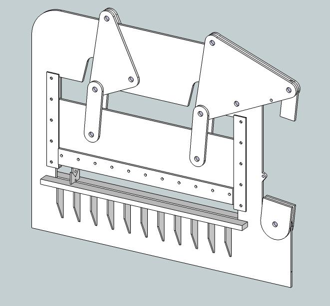
BRAKE 1 by Matthew Dresselhaus, on Flickr

With some dimensions.

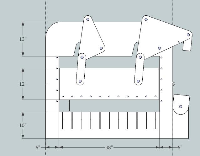
BRAKE 2 by Matthew Dresselhaus, on Flickr


How the dies are placed. They will be laminated together. Based on the dimensions I saw on ebay some normal dies could be purchased and used as well.

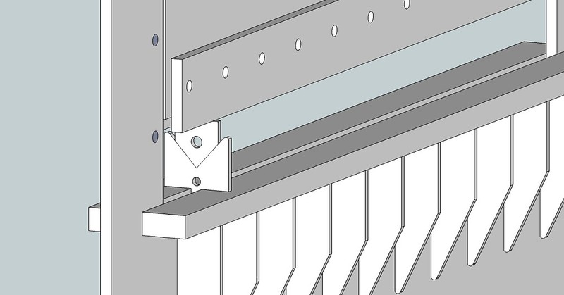
BRAKE 3 by Matthew Dresselhaus, on Flickr


Before I go spend a $1000 on material and turn it into scrap I have a few questions.

1. Is the 1/2" frame strong enough or is there going to be to much deflection in it?

2. Am I right that due to the ratio change in the arms of 1:1.5 the 20 ton ram theoretically become 30 tons of pressure at the die?

3. I was thinking of using 1" grade 8 bolts at the pivot points with 1.5x.25 tube bushings sleeved thru the arms. Should I do something different here?

4. Are there any areas that I have grossly overbuilt or under built?

5. How much weaker would it be if I cut it all out of 1/4" plate? The parts I have drawn as 1/2" would be cut twice and stacked to make them 1/2" thick.

6. Anyone have any comments suggestions or changes I should make?


4x4junkie

Forum Staff Member
TRS Forum Moderator
TRS 20th Anniversary
Joined
Aug 19, 2001
Messages
10,755
Reaction score
583
Points
113
Location
So. Calif (SFV)
Vehicle Year
1990
Make / Model
Bronco II
Engine Type
2.9 V6
Engine Size
2.9L V6
Transmission
Manual
2WD / 4WD
4WD
Tire Size
35x12.50R15
Nice work on the design.

Only thing that really comes to my mind is that the side of the frame where the ram is could have as much as 100,000lbs (50 tons) of tension on it, from the ram itself, as well as from the working load generated by your lever arm. Not looking at it in person it's harder for me to judge it's sturdiness (plus I've yet to build anything myself that operates with that much force), but I'd probably have that side of the frame be a few inches wider. Maybe even make the frame 3/4" thick too.

Using pieces of 1/4" sandwiched together for the frame I don't think will be as rigid. You could put reinforcements along the sides of the frame to improve it's rigidity though.

I'd also go 1.25" on the bolts just to feel safe (maybe even use hardened pins for the pivots themselves).
 

tac1015

New Member
Joined
May 26, 2015
Messages
22
Reaction score
0
Points
0
Vehicle Year
2007
Make / Model
Ford
Transmission
Manual
I work on press brakes every day ,and the American brakes uses die's with 1/2 wide "tongue" that go in the bed of the brake so almost any us style tooling will fit the model you made. I have also make our own dies when I want to prototype something and made them out of 11 ga steel and am surprised how long they last. We use a cnc punch press to make the shape , put 2 1/2 inch hole to push some all thread in and bolt it together , then put it into the brake and put a punch in it and the run a weld bead to weld them into one pcs and what do you know press brake dies made easy. They are not hardened but work for what we need and did not have to pay many thousands of dollars to have them custom made.

Instead of the levers why not just put the ram in the center on the top and have the ram push down , don't have to worry about pins and levers , if you need more tonnage you use a larger v die and it reducers the tonnage required to bend the metal. Rule of thumb on die size is 6 to 8 times thickness of metal to be bent for the die width. Smaller dies make tighter bends but requires more tonnage, larger die more radius bends but less tonnage. You will have a fixed plate on the ram in the back to hold the punch and a removable one in the front to bolt the die in. I would triple up on the ram thickness, use 3 3/8's to 1/2 plates or one 1 inch or so ,and machine, if you can 1/2 off and have the1/2 removable one in the front. The tonnage the punch and die sees is not on the 1/2 tongue it is on the area on either side. The tonnage being applied to the front and back of the tooling means the removable plate in the front will see the same tonnage and the fixed rear so after the punch is installed you bring the dies together and bolt it down , the removable plate has to push on the ram in the same place as the rear so it does not side load the tooling.

Think about using 2 1/2 flat bars for the vertical sides and have the ram be guided between them , doubles the strength in the vertical sections, gives you the guides for the ram that will not let the ram come out under tonnage, you can spring the ram to make it come up when not under tonnage. You wont need a lot of travel from the ram 4 to 6 inches should be enough and you can buy a large bottle jack that will give you lots of tonnage

Good luck, and I thinks it is a great idea to have one to play around with.
 

RockRanger

Member
Solid Axle Swap
Joined
Apr 28, 2008
Messages
387
Reaction score
7
Points
18
Location
Fresno CA
Engine Size
4.0
Transmission
Manual
Nice work on the design.

Only thing that really comes to my mind is that the side of the frame where the ram is could have as much as 100,000lbs (50 tons) of tension on it, from the ram itself, as well as from the working load generated by your lever arm. Not looking at it in person it's harder for me to judge it's sturdiness (plus I've yet to build anything myself that operates with that much force), but I'd probably have that side of the frame be a few inches wider. Maybe even make the frame 3/4" thick too.

Using pieces of 1/4" sandwiched together for the frame I don't think will be as rigid. You could put reinforcements along the sides of the frame to improve it's rigidity though.

I'd also go 1.25" on the bolts just to feel safe (maybe even use hardened pins for the pivots themselves).
Will look at making the one side thicker. Maybe make the other side thinner? Trying to keep t so the main portion fits on a 4x4 piece of steel. The mount for the ram could be cut from a second piece and keyed and welded in if necessary. I don't think my plasma table could cut 3/4" steel well enough to make the main portion. That and me trying to load it would be very difficult with the equipment I have available. Defiantly thinking about larger pins. If I did my calcs right (and I could be wrong) a 1" grade bolt will hold 47 tons. only 66% of the load I would be applying. A 1.5" bolt is over double the strength and with only needing 10 it is not a major cost change. Something to keep in mind for sure.

I work on press brakes every day ,and the American brakes uses die's with 1/2 wide "tongue" that go in the bed of the brake so almost any us style tooling will fit the model you made. I have also make our own dies when I want to prototype something and made them out of 11 ga steel and am surprised how long they last. We use a cnc punch press to make the shape , put 2 1/2 inch hole to push some all thread in and bolt it together , then put it into the brake and put a punch in it and the run a weld bead to weld them into one pcs and what do you know press brake dies made easy. They are not hardened but work for what we need and did not have to pay many thousands of dollars to have them custom made.

Instead of the levers why not just put the ram in the center on the top and have the ram push down , don't have to worry about pins and levers , if you need more tonnage you use a larger v die and it reducers the tonnage required to bend the metal. Rule of thumb on die size is 6 to 8 times thickness of metal to be bent for the die width. Smaller dies make tighter bends but requires more tonnage, larger die more radius bends but less tonnage. You will have a fixed plate on the ram in the back to hold the punch and a removable one in the front to bolt the die in. I would triple up on the ram thickness, use 3 3/8's to 1/2 plates or one 1 inch or so ,and machine, if you can 1/2 off and have the1/2 removable one in the front. The tonnage the punch and die sees is not on the 1/2 tongue it is on the area on either side. The tonnage being applied to the front and back of the tooling means the removable plate in the front will see the same tonnage and the fixed rear so after the punch is installed you bring the dies together and bolt it down , the removable plate has to push on the ram in the same place as the rear so it does not side load the tooling.

Think about using 2 1/2 flat bars for the vertical sides and have the ram be guided between them , doubles the strength in the vertical sections, gives you the guides for the ram that will not let the ram come out under tonnage, you can spring the ram to make it come up when not under tonnage. You wont need a lot of travel from the ram 4 to 6 inches should be enough and you can buy a large bottle jack that will give you lots of tonnage

Good luck, and I thinks it is a great idea to have one to play around with.
What you are saying about the dies is what I am after. This wont be a machine seeing thousands of cycles a day so I think some mild steel dies will hold up for my needs.

I could use a larger ram but I already have a 20 ton ram. Plus as you go bigger the air powered ones get expensive quick. Eventually they are more then just going full hydro. Plus a 20 ton jack is easy to find. If the 20 isn't big enough I could always swap a larger one in assuming the rest of design is capable of the extra pressure.

I do see what you are saying on the 1/2" plate sides and am thinking hard about it.

Thanks for the feedback. I know with the pressure this will see someone (me) could get hurt badly so that is why I am looking at different opinions before I build it.
 

alwaysFlOoReD

Forum Staff Member
TRS Forum Moderator
TRS Banner 2012-2015
TRS 20th Anniversary
Joined
Apr 13, 2009
Messages
13,945
Reaction score
5,088
Points
113
Location
Calgary, Canada
Vehicle Year
'91, '80, '06
Make / Model
Ford, GMC,Dodge
Engine Size
4.0,4.0,5.7
Transmission
Manual
2WD / 4WD
4WD
Could you use two 20-ton rams with a tee for the air or oil?
 

RockRanger

Member
Solid Axle Swap
Joined
Apr 28, 2008
Messages
387
Reaction score
7
Points
18
Location
Fresno CA
Engine Size
4.0
Transmission
Manual
The problem with two rams is getting them to stay synced so that they move the same amount. If one sees more load then the other it will move slower and then the bend will be off.
 

tac1015

New Member
Joined
May 26, 2015
Messages
22
Reaction score
0
Points
0
Vehicle Year
2007
Make / Model
Ford
Transmission
Manual
Think about this one, make 2 plates exactly the same out of 1/2 steel and bolt them together as the main "bridge" portion of the brake. Doesn't matter if you keep you design or have a ram on the top, you will contain the moving head of the brake between 2 pcs of steel, you can put guide bearings on each side to guide the ram evenly , have a very strong frame because it is made with 2 pcs of steel that are made out of one pcs of steel.
No matter how you make the ram move, the side bearings will guide it straight, providing you have the side of the head smooth straight and parallel . Use 4 bearings with say 3/4 inch shaft hole, 2 on each side, you can then fit the head so it travels smooth and straight and you shouldn't side load the brake. The bearings can take a lot of load and keep it moving smoothly .The plats will be roughly square in shape, have a large cutout in the center and you can use the drop for other parts you need to make.

I do like you solid works model, use solid works to make all the cnc mill programs , and you can even make a moving assembly of the brake to see it work. I could measure , say a 2 inch die we use on our brakes, to give you a size to make you dies if you want.
 

Sponsored Ad


Sponsored Ad

Members online

Member & Vendor Upgrades

For a small yearly donation, you can support this forum and receive a 'Supporting Member' banner, or become a 'Supporting Vendor' and promote your products here. Click the banner to find out how.

Truck of The Month


Shran
April Truck of The Month

Recently Featured

Want to see your truck here? Share your photos and details in the forum.

Follow TRS On Instagram

TRS Events

25th Anniversary Sponsors

Check Out The TRS Store


Sponsored Ad


Sponsored Ad

Sponsored Ad


Amazon Deals

Top