Late comer but have some suggestions
No on the wiring harness, there would be a lot more codes if wires were broken/disconnected
Trouble codes are very good to get but you need to look them up on a full list, because most sensors/controls have 2 to 6 different codes that each mean something slightly different
Ford 3-digit code list here:
https://www.therangerstation.com/tech/obd-i-diagnostic-trouble-code-dtc-applications-ford-3-digit-codes/
And once you have the codes CLEAR them, if in doubt disconnect one battery terminal for 5min
Restart the engine and let it warm up, CEL(check engine light) should come back on
Shut off engine and recheck codes
Computers tend to hold old codes in memory a long time, even one off codes, so best to chase current issues than an older one thats no longer an issue, lol
First a bit on how sensors work and codes are set
Sensors all share a 5volt power supply that is inside the computer, its called a Reference power supply, doesn't matter if its 4.8v or 5.3v because all the sensors share it and computer has it so it can "reference" that voltage to the RETURN voltage to see what sensor sees/data
Controls are solenoids, relays and IAC Valve, these get 12volts with key on, computer will GROUND these to open or close them, control them, and it will SEE that 12volts on its control wire(ground wire) with key on
Computer will set specific codes if it does not see "power"/voltage on its Return or Control wires with key on
Start with ECT code 116
116 (O,R) Engine Coolant (ECT) sensor out of range – ECT
117 (O,M) ECT sensor is/was low or grounded – ECT
118 (O,M) ECT sensor is/was high or open – ECT
Computer picked 116, out of range
Not 118 "open"/disconnected
So wiring is probably OK, make sure its the correct 2 wire ECT sensor and its plugged in
Range is 0.3v(Over heated) to 3.5v(-30degF)
On the ECT there will be a Grey/red wire, that's the 5v IN, all sensors have this wire
You can use a sewing needle to pierce any wire to read its voltage, won't hurt the wire, and you can get "needle probes" for Volt Meters
Test the RETURN wire, see what voltage it shows, cold test is fine
1994 will also have a 1 wire Temp Sender for dash board gauge, it a 12volt sender, the ECT looks similar but not the same inside
ECT, in essence, runs the electronic Choke, cold outside temp and engine needs to be choke, rich fuel mix and high idle, computer does this on cold starts
ECT tells computer how rich and how high the idle should be
On Cold Start if you get high idle that slowly drops as engine warms up then ECT is most likely OK
MAF sensor, just FYI this is there to read the WEIGHT of the incoming air, computer already KNOWS its running a 3 liter engine, so knows exactly how much air is coming in at any RPM
MASS air flow sensor, mass = weight
157 (R,M) Mass Air Flow signal is/was low or grounded – MAF
158 (O,R,M) MAF sensor is/was high or short to power – MAF
159 (O,R) MAF sensor is/was out of range – MAF
159 so not a wiring issue, out of range issue
MAF sensor has 4 wires
2 are for the internal heater, a 12volt(key on) and a Ground wire, no connection to sensor part, just a heater, same as O2 sensors have
Other 2 wires are for the sensor, 5v IN and RETURN
MAF sensor is a "main" sensor, unplugging it tells the computer to stay in OPEN LOOP where it only uses tables in memory to calculate air/fuel mix
Should be a Red wire(12v key on) and a Black wire(ground)
Then a blue/red and tan/blue wire for the sensor
Thinking the tan one is the 5v and blue is return but test them with key on engine OFF first
Also just as a test, unplug the 3 wire connector on Throttle Position Sensor(TPS)
Plug in MAF and see if engine runs better
The TPS position is used to set the range of what MAF should show at any given time, same as ECT
565 (O) Canister Purge 1 solenoid/circuit failure – Solenoids
This wouldn't cause engine issue and its most likely either unplugged or a bad solenoid
EVAP system is what this controls, it sucks air out of the gas tank while you drive to prevent gas fumes from polluting the air as the gas sloshes around in the tank
In the engine bay there will be a charcoal canister, usually mounted on the rad support, has a hose to gas tank and another hose to intake, on this hose will be a solenoid valve, hose in and hose out, 2 wires, red(12v) and grey/yellow ground from computer
565 means computer is not seeing 12v on this ground wire with key on, so unplugged or bad solenoid
I would fix the ECT circuit first, because outside temp(cold engine) is used to see if MAF readings are correct
So if ECT is telling computer its 150degF on cold start the MAF readings would be "out of range"
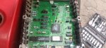
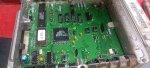
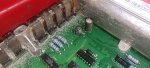
There are 3 capacitors in the computer that should be changed if you have it out
Usually blue, seen in this picture:
http://www.auto-diagnostics.info/ford_eec_iv
They tend to leak after 20+ years, and are cheap to replace
Must match uF on each exactly
But higher voltage replacement is OK to use, i.e. 30v can be replaced with 100v buy NOT 16v
These types of Caps(radial) can get a domed top before leaking, so if the top is not FLAT its on its way out
On my 1994 4.0l a Cap looked fine but when I moved with my finger it just fell off, lol
Also with computer out you can test the wires of the effected sensors
Just to be sure there are no corroded connections
0 ohms is what you should see with probe at each end of a wire
1994 3.0l Engine wiring diagrams below