• Welcome Visitor! Please take a few seconds and Register for our forum. Even if you don't want to post, you can still 'Like' and react to posts.

How to troubleshoot MAF harness?


Joined
Aug 11, 2020
Messages
36
Reaction score
35
Points
18
Location
St. Petersburg
Vehicle Year
Multiple
Make / Model
Rangers
Transmission
Automatic
2WD / 4WD
2WD
Total Lift
stock
Total Drop
stock
Tire Size
stock
My credo
I don't subscribe to causes that are compelled by irrational fears.
I'm having some problems trying to troubleshoot a check engine code on my Thunderbolt (2002 Ranger XLT 4x2 4.0 V6 5 speed auto), P0112. The code is being thrown because the IAT is picking up a temperature that is out of range. I have already replaced the MAF/IAT sensor and cleared the code only to have it return after about half an hour of driving. I have a 2002 ford ranger service manual and I can't seem to track down in the manual a diagnostics procedure for TSing the MAF harness. I suspect it's the wiring harness but I don't want to buy the harness and spend the time splicing the plug only to find out I have a short further up the chain, or something else.

The truck for the most part idles and runs fine; a couple of times (as in, literally twice) in the past six weeks or so it has stumbled and stalled, but started right back up and ran perfectly fine afterwards. When I pull the harness on the MAF while the truck is running, there's an audible change in the way it runs as the ECU resets to a default fuel table. Researching this on the internet turned up an old post on another forum that I couldn't make much sense out of involving the use of safety pins to pierce the harness and what appears to be incorrectly-identified wire colors.

I searched online and can't find a copy of the Powertrain Control & Emissions Diagnosis service manual (for free) anywhere, which I'm pretty sure has the procedure I'm looking for. Does anybody have the procedure for troubleshooting the MAF/IAT harness before I go throw money and time at an undiagnosed problem?


franklin2

Well-Known Member
Joined
Dec 24, 2019
Messages
3,409
Reaction score
1,750
Points
113
Location
Virginia
Vehicle Year
1984
Make / Model
Bronco II
Transmission
Manual
You are doing all the right things. You sometimes have to put down the code readers and just physically use your eyes and ears to find it. I would unwrap that harness and pull on each individual wire all along their length. If you find a stretchy spot, that is not good. Also look for a place where it is prone to vibration or being pulled on that over time might cause a problem. Hopefully you can find the bad spot and just repair the wiring.
 
Joined
Aug 11, 2020
Messages
36
Reaction score
35
Points
18
Location
St. Petersburg
Vehicle Year
Multiple
Make / Model
Rangers
Transmission
Automatic
2WD / 4WD
2WD
Total Lift
stock
Total Drop
stock
Tire Size
stock
My credo
I don't subscribe to causes that are compelled by irrational fears.
I'm looking for something on how to use a multimeter to test the wires and what are the appropriate voltages so I can at least isolate which wire is failing. I'm not an electrician and am really struggling here to figure out how to diagnose the problem. I appreciate the support, but I'm somewhat blind here on how to look for the problem. I'd be surprised if I had something as simple as a clean break.
 

franklin2

Well-Known Member
Joined
Dec 24, 2019
Messages
3,409
Reaction score
1,750
Points
113
Location
Virginia
Vehicle Year
1984
Make / Model
Bronco II
Transmission
Manual
Here's a diagram below. Looks like the wires you are concerned with for the temp sensor is a grey and a grey/red stripe wire. The grey will have a voltage from the computer, the grey/red is the "signal ground" from the computer. I would imagine the power supply for this is 5v dc. If you unplug the connector, you should have 5v on the grey wire with the key in run. That is with the meter on DC volts, the red lead of the meter on the grey wire, and the black lead of the meter on the grey/red wire.

Once you got that setup, you could do your wiggle testing again and see if you lose this voltage.
 

Attachments

RonD

Official TRS AI
TRS Technical Advisor
Joined
Jun 2, 2012
Messages
25,363
Reaction score
8,369
Points
113
Location
canada
Vehicle Year
1994
Make / Model
Ford
Transmission
Manual
In a 2002 4.0l Ranger there would be a 6 wire MAF

In 2002 the 2 outside wires are for the IAT(air temp) sensor, pins 1 and 6

The grey/red wire is shared with other sensors, like ECT, TPS, DPFE, ISS and OSS, so lots of codes if that wire should fail

The "safety pin" is used to pierce a wire while its connected, it makes a small hole in the insulation so won't hurt the wire and its metal so conducts electricity so you can read voltages or ohms on that wire in real time
You can get Volt/ohm meter probes with Needle Tips that do the same thing, allows you to read voltages or OHMs thru the insulation without disconnecting the wire

Sewing needles work as well but safety pins are just easier to push into the wires, better grip

Do as Franklin said

You can also test ohms on the grey/red wire at MAF to a grey/red wire at say the TPS(throttle sensor) should be a direct connection
Set Meter to OHMs lowest scale if it has that option, say 200 ohms
Touch the two meter probe tips together, should see display change to 0 ohms, "direct connection"
Key off
Unplug MAF connector and TPS connector
Put one probe on MAF sensor grey/red wire and the other probe on TPS grey/red wire
Should see 0 ohms, direct connection, because its a shared wire
If not then that's your problem, grey/red wire is broken at some point from its shared splice with TPS to the MAF connector

It's usually easier to run a new wire than to find a broken wire in a harness

The grey IAT wire runs to pin 39 on the large, 104 pin, PCM(ECU) connector on the firewall
You can do same OHM test on that wire as well but use the safety pin method at the large connector so you don't have to pull the connector off

If both wires test as OK and you have a new IAT sensor, then P0112 code is an issue inside the PCM, could be in the large connector so take it off and look for corrosion on the pins and slots

All the sensors run on 5volts and signal to PCM is less, so even a little corrosion will cause an issue as voltage drops too low
 
Joined
Aug 11, 2020
Messages
36
Reaction score
35
Points
18
Location
St. Petersburg
Vehicle Year
Multiple
Make / Model
Rangers
Transmission
Automatic
2WD / 4WD
2WD
Total Lift
stock
Total Drop
stock
Tire Size
stock
My credo
I don't subscribe to causes that are compelled by irrational fears.
Hey thanks, both of you. I'll run through these checks and report back with findings. Might take me a couple of days.

Just a quick note, from the stuff I did yesterday, the wire on pin 6 was reading 4.5V instead of 5 when it was disconnected; we dismissed this originally as "cheap harbor freight multimeter margin of error," but would half a volt be enough to cause this problem? I also noticed on the same pin, when the harness was plugged in, the wire would return zero (specifically 0.03V). I thought this was unusual because the pin was probed into the same spot both plugged in and not (just before the harness). It didn't seem to make sense that a short in the plug would cause the 6 pin to go from 5V to 0V when probed before the supposed short.
 
Last edited:

RonD

Official TRS AI
TRS Technical Advisor
Joined
Jun 2, 2012
Messages
25,363
Reaction score
8,369
Points
113
Location
canada
Vehicle Year
1994
Make / Model
Ford
Transmission
Manual
Testing sensor voltages can be odd, lol

The computer uses a reference voltage or a reference ground for sensors, these are called pull up or pull down circuits
What the computer is looking at is the difference between the "reference" and the "return" wires on the sensor

So even IF the "reference" is not an exact voltage or ground it doesn't matter since the difference is what matters
The reference voltage is INSIDE the computer, and its used to see the difference on the return voltage

Yes, if there was corrosion or bad connection on Reference wire, then Return would not be correct since the computer is using a different internal Reference

All sensors are 5volt but that's operating voltage not necessarily what you would see specifically "powering" the sensor
You can test another sensor and if it showed 5.1v and IAT showed 4.5v then that could be a cause for concern, as they should both have the same "reference"

Testing the Return/signal wire often gives best results, engine running, wires connected
IAT return voltage is well documented
ECT and IAT use the same scale

Seen here: https://aws1.discourse-cdn.com/arduino/original/4X/b/4/c/b4cc7d9d26234f37a1d895babb6992bb2d66921c.gif

So if outside temp is 70degF then key on engine off you should see about 3v
 

franklin2

Well-Known Member
Joined
Dec 24, 2019
Messages
3,409
Reaction score
1,750
Points
113
Location
Virginia
Vehicle Year
1984
Make / Model
Bronco II
Transmission
Manual
Yes, in the diagram see that dotted box with "A147" near it? Everything inside that dotted box is inside the computer. That ziggity line inside the box is a internal resistor. On top of the resistor is 5v inside the computer. Below that resistor you see a tap off, that is inside the computer also and that is where it's getting it's reading.

It's called a voltage divider. Let's say the internal resistor is 1000 ohms. If your sensor (the resistor symbol with the arrow in the diagram) happens to be 1000 ohms also, then that tap off inside the computer will be 2.5v, half of 5v.

If your sensor happens to be zero ohms, then the tap off inside the computer will read zero volts, all of the 5v will be dropped across that internal 1000 ohm resistor, so the internal tap off inside the computer will only see 0 volts.
 
Joined
Aug 11, 2020
Messages
36
Reaction score
35
Points
18
Location
St. Petersburg
Vehicle Year
Multiple
Make / Model
Rangers
Transmission
Automatic
2WD / 4WD
2WD
Total Lift
stock
Total Drop
stock
Tire Size
stock
My credo
I don't subscribe to causes that are compelled by irrational fears.
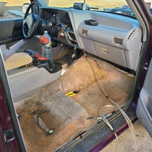
I've managed to troubleshoot this partially, but I've had to park on this issue for now and turn my attention to other tasks. I was able to determine that the harness itself is fine and the problem is further upstream, so I'd like to thank you guys for the help. I'll use this information when I revisit the problem later to try to solve it.
 

Sponsored Ad


Sponsored Ad

Staff online

Members online

Today's birthdays

Member & Vendor Upgrades

For a small yearly donation, you can support this forum and receive a 'Supporting Member' banner, or become a 'Supporting Vendor' and promote your products here. Click the banner to find out how.

Truck of The Month


Shran
April Truck of The Month

Recently Featured

Want to see your truck here? Share your photos and details in the forum.

Follow TRS On Instagram

TRS Events

25th Anniversary Sponsors

Check Out The TRS Store


Sponsored Ad


Sponsored Ad

Sponsored Ad


Amazon Deals

Top