Dynamic tire spin balancer
In my ongoing battle of trying to get my Goodyear MT/R-Kevlar tires balanced (and in the process finding out what a POS the bubble balancer sold at the local Chinese-tools store is,

at least the return was hassle-free), I finally decided to build myself a real unit that I can also do actual spin tests on.


(click pics for bigger)
If you're patient enough, this unit is capable of static-balancing a tire to within 1/2 oz for bigger tires (>33") and 1/4 oz for smaller tires (<30"). Imbalances of 1 oz and 1/2" oz (respectively) will be readily obvious however.
Dynamic imbalance is the prime cause for steering wobble or shimmy, so it should help eliminate those issues also.
If your tire shop can't (or doesn't want to) balance large oversize tires (or charges obscene amounts to do it), then just another reason to read on.

To build it:
First, weld together a stand like shown that will fit around the largest tire you plan to balance (I used 1x2x.120" rect. tubing).
Next you'll need a spindle & rotor from a 2WD vehicle with the lug pattern you need (I sourced mine from a '86 Ranger at a junkyard).
Make sure the brake rotor you get is good (not warped), otherwise this will negatively affect your spin results.
Trim the "fat" off it until you're down to just the spindle itself and a portion of the knuckle about 6-8" long

Make a pair of brackets like shown that will fit around the stand's frame to stabilize the spindle (I used various pieces of strip steel 2" wide, 1" wide, and 1/2" wide, all are 1/8" thick except the 2" is 1/4" thick). Leave about 1/16" of 'wiggle room' between the guide prongs and the stand (grind the inside of the prongs a little bit if necessary)
Make a "hook" on the spindle and a "pocket" on the stand so you can attach the spindle to the stand while it's stood upright (two offset pieces of strip steel stacked on each other forms the pocket)

Weld an eyebolt (threaded end cut off) into the rear of the spindle and attach a short piece of steel cable between it and the stand using a 2nd eyebolt (I used 1/8" cable and 1/4" x 2" eyebolts)
Weld a piece of 1/2" or 3/4" wide angle steel to the stand so that it's end will be about 1" from the rotor's surface

Hook the spindle to the stand and assemble the rotor & bearing onto the spindle.
To minimize rotational drag as much as possible, hone out the bearing seal using a drum-sander bit on your rotary tool (Dremel, etc.) so that the seal has about a 1 mm gap around the spindle (you could also leave the seal out entirely, however this will leave the bearing more exposed to dust, which can affect the balancer's performance).
Lubricate the bearings with engine oil (don't use grease), and tighten the bearing nut just barely finger-tight (leaving a couple thousandths free play in the bearing).

____________________________________________________
Using the balancer:
Static tire balancing:
1.
Mount your tire & wheel to the balancer (use all lug nuts, missing nuts will affect the balance)

2.
Identify any heavy (out of balance) area of the tire by allowing gravity to slowly bring it to the bottom.
3.
Secure stick-on wheel weights to the inside of the rim (as close to centered as possible) opposite from where the imbalance is. Continue repeating until you have established good static balance of the tire & wheel assembly (I like to tape the weights in place initially so that I can remove/reposition them if needed).

Dynamic spin balancing:
4.
Once good static balance is established, disengage the spindle hook from the stand and place the stand with the tire facing downward so that the spindle assembly is supported by the steel cable.
5.
Spin the tire up to approximately 300-350 RPM, or about 5-6 rotations per second (put your angle grinder or a die grinder against the tire tread to spin it up).
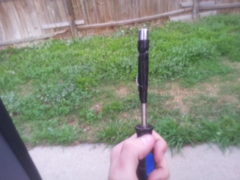
Stabilize the spindle assembly by firmly pressing the guide prongs (red arrows) up against the stand with your thumbs for about 8-10 seconds (this is to eliminate any slow-speed wobbling (precession) of the spinning tire).

6.
Take a marking pen (Sharpie, etc.) and carefully place it within the angle steel bracket directly above the spinning rotor. Very slowly bring the tip down until it just barely contacts the rotor, leaving a mark on the rotor.
7.
Slow the tire to a stop by placing a wood 2x4 or something similar against the tread (don't try to stop it with your bare hands unless you like friction burns!)
8.
Examine the mark from your pen... If it's uniform all the way around the rotor, skip to step #9.
If the mark occurs only partway around the rotor, add weight at the inside edge of the wheel rim immediately next to where the mark is thickest/darkest on the rotor, and another
equal amount of weight to the OUTSIDE edge of the rim 180° opposite of the mark, then repeat steps #5 thru #7 (a paper towel soaked with brake cleaner or acetone can be used to remove previous marks from the rotor).

Continue repeating until a uniform mark that fully encircles the rotor is formed during step # 6.

9.
Dismount the tire from the balancer. It is now ready to put back on your vehicle.

Note that if your tires are more than a few millimeters out of round (as I discovered my MT/R-Ks are), they may never ride perfectly smooth. However the improvement over what they were before (after trying to deal with them to no avail at the tire place) was quite dramatic.
Happy balancing!


")


