• Welcome Visitor! Please take a few seconds and Register for our forum. Even if you don't want to post, you can still 'Like' and react to posts.

BW1354 Manual-Shift Rebuild (by the book)


lowspeedpursuit

Active Member
Joined
May 6, 2022
Messages
204
Reaction score
150
Points
43
Location
DE
Vehicle Year
1994
Make / Model
B2300
Engine Type
2.3 (4 Cylinder)
Transmission
Manual
2WD / 4WD
4WD
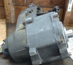
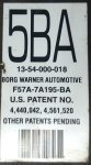
After finishing my 4wd swap on my '94, and taking it off-road for the first time, I drove across the county and back, and by the time I got home, I had a pretty bad grinding noise on takeoff. I had already rebuilt the trans (input shaft bearing) and the rear diff (twice, thanks Yukon). The noise wasn't as bad with the t-case in neutral, and the rear diff looked fine, so I bought some parts and pulled the transfer case. This case is from a '95, but I don't think there are super aggressive differences by year.

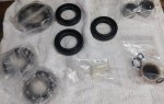
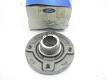
Bearings, Seals, Bushing, and Plastic Fork Guides:
https://www.transmissionpartsdistributors.com/bw1354-transfer-case-rebuild-kit-fits-bronco-ii-ranger-explorer-mazda-b-trucks-86-08-bk1354/

Chain:
https://www.rockauto.com/en/moreinfo.php?pk=10582420
https://www.amazon.com/dp/B09BYWX396 (this chain was cheaper, but it's out of stock right now)

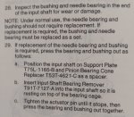
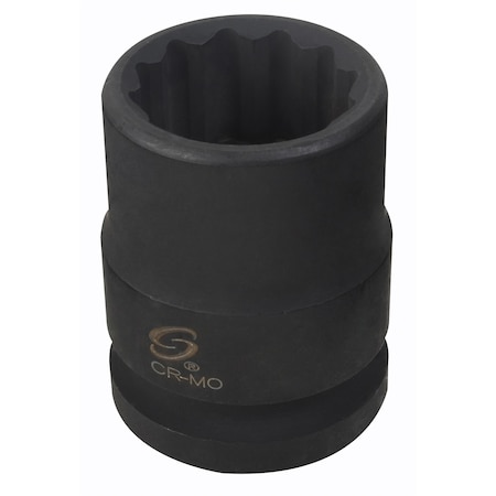
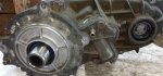
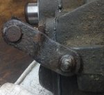
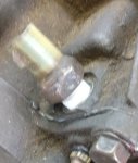
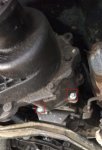
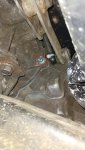
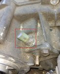
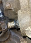
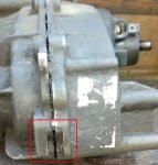
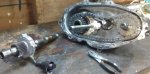
The t-case is held in by the driveshafts (rear: 12mm 12pt) (aftermarket front: 13mm), speedo sensor (7/16"), 4x4 dash indicator wiring (on top, towards the trans), vent hose (behind the shifter linkage), and five bolts (13mm). You don't have to remove the shift linkage. The two bolts on the top are easier to reach by removing the floor panel over the trans, but you can get them from the bottom with an extension and swivel. The transfer case is light enough, and clocked far enough off horizontal, that it's easier to press it in and out yourself than to bother with a trans jack. Once it's out, pull the fill and drain plugs on the back and drain the fluid.

BW1354_bolt_lower.jpg BW1354_bolt_passtop.jpg BW1354_bolt_driversmid.jpg BW1354_bolt_driverstop.jpg BW1354_drainplugs.jpg

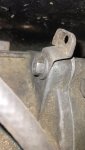
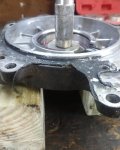
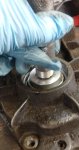
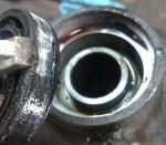
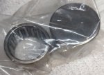
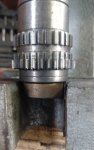
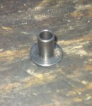
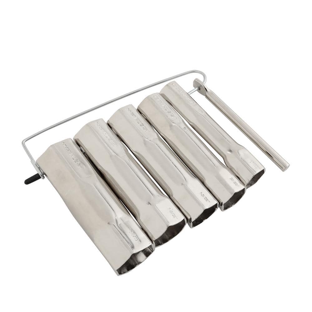
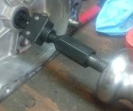
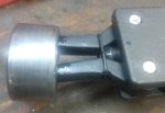
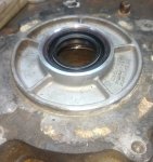
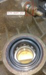
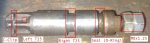
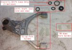
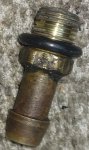
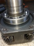
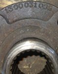
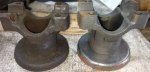
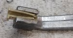
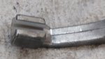
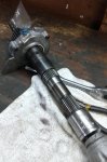
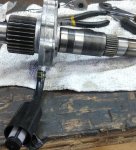
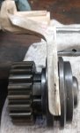
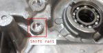
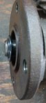
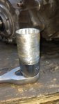
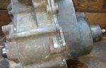
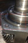
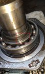
Then, you need to pull the output yokes (30mm, front requires "thin-wall"). Neither of mine needed a slide hammer. The service manual also says to pull the 4wd sensor at this time (7/8" deep). I didn't have a 7/8" deep, so I used vice grips. I also didn't have timely access to "thin-wall" sockets (and they apparently cost 3x as much anyway), so I bought a regular 30mm deep for $11 and clearanced the outside with an angle grinder and an impact driver. You don't need to remove very much material. I didn't want to impact with the modified socket, so I used a breaker bar, with a big pipe wrench holding the yoke. The last pic shows how the seals go on the output shafts.

BW1354_4wdsensor.jpg BW1354_30mmthinwall.jpg BW1354_rearflangeparts.jpg BW1354_frontyokeseal.jpg

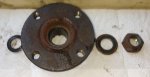
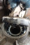
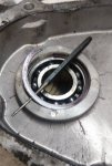
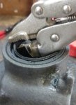
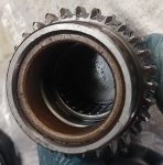
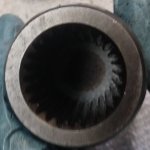
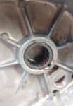
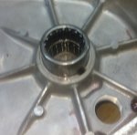
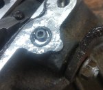
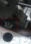
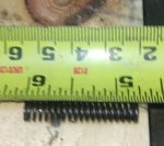
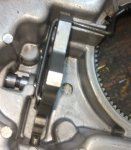
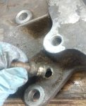
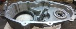
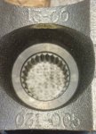
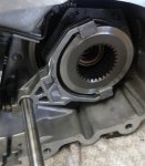
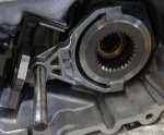
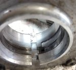
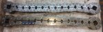
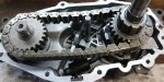
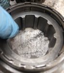
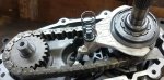
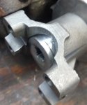
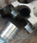
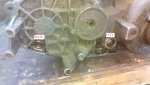
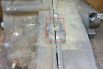
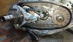
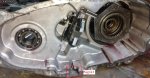
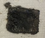
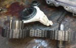
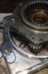
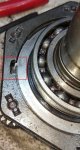
At this point you can take out 9x bolts (15mm) and split the case. There are three pry points: top center, driver's edge, and bottom inline with the input and rear outputs. You can jam a 3/8" or 1/2" extension in at these points and wiggle it back and forth. My case didn't want to fully separate, so I also gently pried on the mating surfaces themselves--which is bad practice--using a flat screwdriver with tape over the end, wrapped in a paper towel. Finally, I smacked the front output shaft with a dead-blow hammer. As a result of pushing the front output shaft backwards, you can see that all the guts stayed in the rear half of my case. Per the service manual, you would expect the rear half to separate cleanly, and the guts to stay in the front. You can also see a fair amount of metal on my magnet, although nothing totally insane.

BW1354_prypointtop.jpg BW1354_prypointdrivers.jpg BW1354_prypointbottom.jpg BW1354_caserearhalf.jpg BW1354_casefronthalf.jpg BW1354_casedirtymagnet.jpg

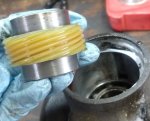
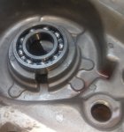
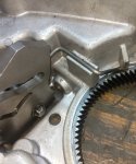
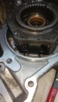
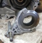
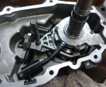
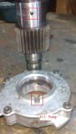
It looks like I didn't take a picture of the range fork removal, and the pics aren't great in general, but basically at this point you can just start taking shit apart. My disassembly is going to be in reverse of anyone whose guts stayed in the front half of their case. If you want to remove the oil pump from the main/output shaft, rotate the pump freely around the shaft until the notch on the pump lines up with the retaining pin on the shaft. At this point the pump will slide right off (thanks irate4x4), but you have to pull firmly. The pickup tube is attached to the pump with an ordinary spring clamp.

BW1354_removemainshaft.jpg BW1354_removechainmodefork.jpg BW1354_removecaserearempty.jpg BW1354_removeoilpump.jpg

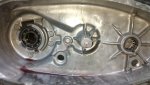
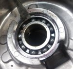
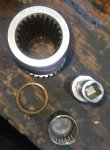
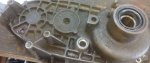
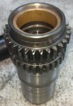
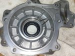
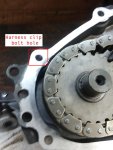
Now you can take the mostly empty front half of the case, flip it around, and remove 6x bolts (15mm) retaining the front face around the input shaft. It's RTV'd on, so I beat it with a dead-blow hammer around each of the ears. The face will come off with the input shaft and planetary assembly attached. A big snap ring with long tangs holds the face to the assembly via a groove in the input shaft bearing. When you spread the tangs with snap ring pliers, the face will fall off the input shaft.

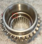
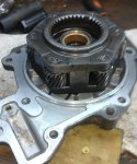
Flip the assembly over so the input shaft is facing up. A large internal snap ring holds the input shaft to the planetary. Smack it around rotationally until one of the ends is in one of the notches, then you can get your snap ring pliers in there. Pry up underneath to get it started, then work the entire ring out and up, and remove the input shaft/sun gear assembly from the planetary.

BW1354_inputassemblyfacesnaptangs.jpg BW1354_inputplanetaryinternalsnap.jpg BW1354_inputplanetaryinternalsnapinprogress.jpg

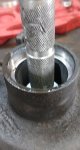
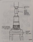
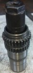
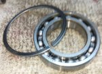
Now the most difficult step of all the work I've done so far: getting the input shaft bearing off the input shaft. First, remove the external snap ring. Then, the service manual says to use a bearing puller, but mine shattered, and I've been jerry-rigging solutions ever since. For this, I held the bearing tightly in my vise with the input shaft pointing down, and hit the input shaft upwards from the bottom with a brass hammer. Popped right out.

BW1354_inputbearingexternalsnap.jpg BW1354_inputbearingexploded.jpg

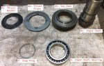
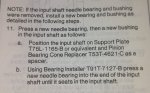
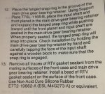
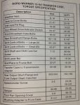
To make sense of the references in the last picture, as well as how everything fits together, here's the 1994 service manual's official exploded view and parts list:

BW1354_serviceexploded.jpg BW1354_serviceexplodedlist.jpg

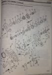
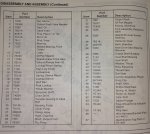
That's as far as I got on the first day. I still need to pop the rest of the bearings and seals out of the case, test the oil pump, and figure out how to get the pocket needle bearing out of the inside of the input shaft. I might do that tomorrow, but reassembly is a ways away, since my new chain isn't scheduled for delivery until Monday.

I also need to assess whether the degree of play I have in the input shaft and planetary assembly is acceptable. I don't see any play specs in the manual, so input is welcome.
 
Last edited:


lowspeedpursuit

Active Member
Joined
May 6, 2022
Messages
204
Reaction score
150
Points
43
Location
DE
Vehicle Year
1994
Make / Model
B2300
Engine Type
2.3 (4 Cylinder)
Transmission
Manual
2WD / 4WD
4WD
Day two: removing old bearings and seals. Laid out the rebuild kit. All three large seals appear identical. Both output shaft bearings appear identical. Have some o-rings I have yet to see in teardown, probably from the 4x4 sensor, breather, and shift rails. Also not sure where the smaller pair of fork guides go. It's possible there's another version of this case where the entire mode fork isn't made of plastic.

BW1354_overhaulkit.jpg

Hammered out the input shaft seal first, since its bearing was already out of the way. Next was the front output seal and bearing. For both output shafts, you do not press or hammer the bearing and seal out together as a unit. The seals pry out from the outside (I used small vice grips with duct tape over the lower jaw), then a snap ring retains the bearings from inside. These snap rings are a pain in the ass, because they don't have proper pry points, and it makes me uncomfortable to pry against aluminum. With the snap rings removed, the bearings will press inwards from the outside.

BW1354_teardown_inputseal.jpg BW1354_teardown_frontoutputseal.jpg BW1354_teardown_frontoutputsnapring.jpg BW1354_teardown_frontoutputbearing.jpg

Repeat the same process for the rear output shaft, but in this case the speedometer drive gear is also inside, in the gap between the seal and bearing. It appears symmetrical. I honestly have no idea how it engages with the main/output shaft.

BW1354_teardown_rearoutputseal.jpg BW1354_teardown_rearoutputlookin.jpg BW1354_teardown_rearoutputspeedogear.jpg BW1354_teardown_rearoutputsnapring.jpg BW1354_teardown_rearoutputbearing.jpg

Pulling out the needle bearings was always going to be more difficult, but I expected the one inside the input shaft to be the problem, and the one that holds the back end of the front output shaft to be easier. In fact, it was the reverse. The service manual clued me in to the fact that the input shaft needle bearing isn't actually blind. With the bearing removed, the shaft is hollow straight through. So, you just press the bearing out from the front of the input shaft. The brass bushing will come out as well. You can see that the service manual also says "you don't usually need to replace these", but my brass bushing had obvious pitting.

BW1354_overhaulneedlebearings.jpg BW1354_service13a.jpg BW1354_service13b.jpg
BW1354_teardown_inputshaftinsiderear.jpg BW1354_teardown_inputshaftinsidefront.jpg BW1354_teardown_inputshaftpress1.jpg BW1354_teardown_inputshaftpress2.jpg BW1354_teardown_inputshaftpressexploded.jpg

Finally, the needle that holds the rear end of the front output shaft. I was vaguely considering the "bread" method that everyone talks about for pulling clutch pilot bearings, but in this case there were two problems: one, I don't know if I have anything to snugly fit the ID, and two: I feel like the oiling passage would prevent me building pressure to force the bearing out anyway. So, this one is actually still in there. I have to come up with a blind bearing puller of the appropriate size before I'll be able to proceed.

BW1354_teardown_frontoutputneedle.jpg

All in all, not bad progress for a Sunday. I was worried about play in the input shaft before, but both of my output shaft bearings ended up feeling and sounding like they're full of gravel. Hopefully that's the crux of the grinding noise I had, and a normal bearings-and-seals rebuild will be sufficient.
 

Shran

Junk Collector
TRS Forum Moderator
Supporting Member
Article Contributor
V8 Engine Swap
Solid Axle Swap
Truck of Month
Joined
Mar 4, 2008
Messages
8,698
Reaction score
4,798
Points
113
Location
Rapid City SD
Engine Type
V8
Engine Size
5.0
Good work...I am pretty sure I used a slide hammer to remove that pocket bearing when I did one years ago. I had a hook attachment or something like that.
 

lowspeedpursuit

Active Member
Joined
May 6, 2022
Messages
204
Reaction score
150
Points
43
Location
DE
Vehicle Year
1994
Make / Model
B2300
Engine Type
2.3 (4 Cylinder)
Transmission
Manual
2WD / 4WD
4WD
Today is not a progress post. I did do some work, replacing the needle bearing, output shaft bearing, and input shaft seal, but I'll write that up another time.

This post is about me wasting half the morning and temporarily losing part 51, "4L assist roller bushing". One of the seals I hadn't seen yet turned out to be the "shift shaft seal", so I attempted to disassemble the shift cam mechanism.

As it turns out, my shift shaft actually won't come far enough out of the case to clear the cam, and the service manual just says "remove shift shaft", which is less than helpful. In the process of fiddling with it, I lost control of the cam spring, and spent the next half-hour looking for part 51, which goes on the end.

BW1354_p51bench.jpg

This is where it ended up, in the goddamned rafters.

BW1354_p51rafters.jpg

I'm taking this as I sign that I should take the afternoon off to go surfing, so the project gets extended another day.
 

don4331

Well-Known Member
V8 Engine Swap
Joined
Sep 6, 2013
Messages
2,027
Reaction score
1,346
Points
113
Location
Calgary, AB
Vehicle Year
1999
Make / Model
Ford
Engine Type
V8
Engine Size
5.3
Transmission
Automatic
Interesting about the subtle differences between years.

I'm curious about how "gentle" you were with the deadblow hammer to get the front cover off... I've tries "reasonable" amount of force and got nowhere...
 

4x4prepper

Active Member
Joined
Feb 2, 2015
Messages
507
Reaction score
216
Points
43
Location
Atlanta
Vehicle Year
1985
Make / Model
Ford
Transmission
Manual
> This is where it ended up, in the goddamned rafters.

Blew up the pix 400% and I still can't see it :-D

> I also didn't have timely access to "thin-wall" sockets

You might find for the reinstall that the thin wall sockets for shower and faucet valves fit.

(1-5/32 in ?)

It might be off 1/64 or so,but, if you are not using a lot of torque it probably does not make a difference since you took it off with vise grips.

I tried to find it in my bookmarks, but, there is a place that sells deep (6+ inches) thin walled sockets meant for plumbing, BUT, they have them in all sorts of sizes of both SAE and metric. I know I saved it somewhere, after needing a deep thin wall for a water valve, just wish I could find it ...
 

4x4prepper

Active Member
Joined
Feb 2, 2015
Messages
507
Reaction score
216
Points
43
Location
Atlanta
Vehicle Year
1985
Make / Model
Ford
Transmission
Manual
I could not find my plumbing catalog, but, I did find my sunnex catalog, I think this is the socket you need that is thin enough and long enough


I am going to save this thread and re-read it later, I have never totally disassembled a 1350/1354 transfer case before.
 

lowspeedpursuit

Active Member
Joined
May 6, 2022
Messages
204
Reaction score
150
Points
43
Location
DE
Vehicle Year
1994
Make / Model
B2300
Engine Type
2.3 (4 Cylinder)
Transmission
Manual
2WD / 4WD
4WD
I am pretty sure I used a slide hammer to remove that pocket bearing when I did one years ago. I had a hook attachment or something like that.
Good call; I ended up doing the same.
I'm curious about how "gentle" you were with the deadblow hammer to get the front cover off... I've tries "reasonable" amount of force and got nowhere...
I was not particularly gentle. My policy is to grab the right kind of hammer and then absolutely send it. I will say that I didn't really have to beat on mine that hard. The front face was absolutely gobbed in RTV after it separated, but still came apart with very little trouble. As long as you're using a soft hammer, I would also consider carefully tapping on the planetary from the inside. I could also see maybe working a long, soft punch through where the shifter cam lives, or bottoming out a bolt through where the vent screws in.
I could not find my plumbing catalog, but, I did find my sunnex catalog, I think this is the socket you need that is thin enough and long enough
Good info, thank you. That is substantially cheaper than I was turning up (~$35).
 

Shran

Junk Collector
TRS Forum Moderator
Supporting Member
Article Contributor
V8 Engine Swap
Solid Axle Swap
Truck of Month
Joined
Mar 4, 2008
Messages
8,698
Reaction score
4,798
Points
113
Location
Rapid City SD
Engine Type
V8
Engine Size
5.0
Good info, thank you. That is substantially cheaper than I was turning up (~$35).
I just have a normal 30mm shallow 12 point Craftsman socket that I use for yoke nuts. It fits very snug - if it doesn't fit, there is dirt or rust in the way or at least that's what I've found.
 

lowspeedpursuit

Active Member
Joined
May 6, 2022
Messages
204
Reaction score
150
Points
43
Location
DE
Vehicle Year
1994
Make / Model
B2300
Engine Type
2.3 (4 Cylinder)
Transmission
Manual
2WD / 4WD
4WD
Picking up where I left off, the next thing I did was get the front output shaft needle bearing pulled. For this I used the Autozone 57059, a small internal 2-jaw puller slide hammer attachment, for $23 (rentable). I already owned a 5lb slide hammer. At first glance, the puller was designed for hammers with larger threads, but deeper inside the coupler the ID necks down, so it can fit 2 different sizes of hammer shaft.

In order to get the bearing to pull with a 2-jaw, rather than the proper collet-style puller, I had to tighten the absolute piss out of it with I believe a 21mm socket. I then hammered the new needle bearing in, with the old one on top because I didn't have a small enough attachment in my bearing driver kit. The new bearing had a hole in the side, presumably for oil, so I lined it up with the oil passage in the case.

BW1354_frontoutputneedlepuller.jpg BW1354_frontoutputneedlepullerremoved.jpg BW1354_frontoutputneedlepress.jpg

After that, I reinstalled the rear output bearing, snap ring, speedometer gear, and seal. You don't want to press this bearing in using the old one, because it seats deep enough that the old bearing will become press-fit as well, and you'll have to drive them both back out. On closer inspection, the speedometer gear is not completely symmetrical: looking down the bore, one end of the plastic gear has rectangular holes engraved. These were facing rearwards out of the case on removal, so the gear went back in the same way. I also went ahead and reinstalled the drain plug, then set the rear half of the case aside.

BW1354_rearoutputbearingpress.jpg BW1354_rearcasepostrebuild.jpg

Next I installed the new input shaft seal, the front output shaft bearing, snap ring, and seal, and then I worked on the shift shaft seal and cam assembly. The TL;DR here is that having disassembled and inspected everything, there is no point in fully removing the shift shaft unless you specifically need to replace some part of the cam assembly. You can change out the shift shaft seal by removing all the hardware and sliding the shaft out just far enough to expose the o-ring without moving the cam out of position. This will save you an awful lot of trouble with the cam bushing spring that got away from me the other day.

In order to slide the shift shaft out, you remove the two T25 torx screws on and around the front of the shift cam, then you remove the c-clip retaining the end of the shift shaft through the cam. At this point you can pry or pull the shaft out of the case until you see the seal. I threaded some extra nuts onto the end of the shaft and slide-hammered off of them with vice-grips. The threads are M8x1.25.

BW1354_frontfacepostrebuild.jpg BW1354_frontoutputpostrebuild.jpg BW1354_shiftcamtorx.jpg BW1354_shiftcamcclip.jpg

Because I took it all apart, I might as well show how the shift shaft and cam fit together. My shaft was stuck because the metal had a small deformity next to the inner groove that mates with one of the torx retainer screws, which I filed down before reinstallation. It's very important that if you fully remove the shift shaft, you note the correct orientation of the cam with regard to the flats on the end of the shaft, as in the first picture here. The small spring lives inside the cam detent. The large spring I installed with everything else in place, cam-bushing-end first, then pushed the free end down into its groove using a block of wood, while lightly tapping on the part that runs perpendicular. The T25 screws are reinstalled with blue loctite.

BW1354_shiftcamalignment.jpg BW1354_shiftshaftremoved.jpg BW1354_shiftcamdetentspring.jpg BW1354_shiftcamreassemblednospring.jpg BW1354_shiftcamreassembledspringseated.jpg

An aside about fork guides and small seals: per transmissionpartsdistributors' catalog, there are four fork guides in this rebuild kit because this case has two different versions of shift fork. The larger guides are for '91-up Fords, so I won't use the smaller guides (for '90-down Fords and any-year Mazdas) at all. I also believe this kit contains small seals for both electric and mechanical versions of the case, so some of those will go unused in my application.

It seems like the 4x4 sensor could have an o-ring, but the parts diagram doesn't show one, and the large ring in the rebuild kit is too large. I actually ended up installing the small o-ring on my case's vent fitting, not because I think it has anything to do with the seal there, but because I noticed my vent fitting wasn't originally screwed all of the way in. If it was screwed in further, it would protrude appreciably into the shift cam cavity. So, I'm basically using the small o-ring as a stop to easily screw it in to the correct depth on reinstallation.

BW1354_forkguideoringbreakdown.jpg BW1354_frontfaceventcheck.jpg BW1354_ventwithoring.jpg

At this point I was ready to start really putting stuff back together, so I started by installing the needle bearing and brass bushing into the input shaft. The bearing started with the old bearing and finished with a 1-1/16" deep impact socket. It seats all the way down, against the input shaft splines, in order to expose an oil passage. The brass bushing started with the old one and stopped as soon as the old one started to catch inside the input shaft. This isn't all the way down against the lip, but it is the depth I removed the original from, and also per the service manual, "until it seats in the input shaft".

BW1354_inputshaftneedlepress.jpg BW1354_inputshaftneedleoilingpassage.jpg BW1354_inputshaftbushingpressed.jpg BW1354_servicebrassbushing.jpg

Then I reassembled the input shaft to the sun gear, and installed the new input shaft bearing using the old bearing and a brass hammer. All three of the big bearings in my rebuild kit had grooves. For the output bearings, these grooves don't do anything, so their orientation doesn't matter. The groove on the input shaft bearing retains a snap ring, and must face down towards the sun gear. The bearing actually came with a snap ring set into it, but the new ring lacked the long tangs that make this application work, so it was removed and set aside.

The indentations on one side of the thrust plate are 45* offset from the other. Per the manual, the side with the indentations aligned with the ears faces out, away from the sun gear. The thrust washer concavity faces down, towards the sun gear. Once the new bearing is on the input shaft and retained with the small snap ring, the assembly can be reinstalled to the planetary, and retained with the large snap ring.

BW1354_inputshaftbearingstocksnap.jpg BW1354_inputshaftplanetarypostrebuild.jpg

At this point, I realized I needed to clean all the old RTV off of my case's mating surfaces, and that I probably should have done that before installing all of the new bearings. But whatever, I wiped up whatever debris came loose, and blew any leftover pieces off with compressed air. Once everything was clean, I reinstalled the input shaft planetary assembly to the front face of the case. When the snap ring is locked to the assembly, the tangs will be almost all of the way back together (4th picture). If they're further apart (3rd picture), the snap ring isn't seated in its groove.

BW1354_frontcasecleaned.jpg BW1354_frontfacecleaned.jpg BW1354_frontfaceplanetarytangswide.jpg BW1354_frontfaceplanetarytangsnarrow.jpg

Finally, I reinstalled the completed front face to the front half of the case, using Permatex Ultra-Black. Final torque of the six 15mm bolts is 23-30 ft-lbs.

BW1354_servicesealant.jpg BW1354_frontassemblyready.jpg BW1354_frontcasecomplete.jpg
 
Last edited:

Shran

Junk Collector
TRS Forum Moderator
Supporting Member
Article Contributor
V8 Engine Swap
Solid Axle Swap
Truck of Month
Joined
Mar 4, 2008
Messages
8,698
Reaction score
4,798
Points
113
Location
Rapid City SD
Engine Type
V8
Engine Size
5.0
Oh man... all that work and you didn't run the outer case halves through a parts washer??? sinner!!! 🤣 🤪
 

lowspeedpursuit

Active Member
Joined
May 6, 2022
Messages
204
Reaction score
150
Points
43
Location
DE
Vehicle Year
1994
Make / Model
B2300
Engine Type
2.3 (4 Cylinder)
Transmission
Manual
2WD / 4WD
4WD
A digression about Ford, part numbers, and output yokes:

Ford does this irritating thing where they can make it difficult to find the part number you need to actually buy a part that fits your truck, especially for older applications where you're often browsing limited New Old Stock. For example, while I understand "service part numbers" conceptually, I don't know how to find them, or tell service and engineering part numbers apart. Besides that, you can see in my first post that the entire transfer case parts list gives "base" part numbers only, without prefix or suffix. I'm not sure why they do this. It would be different if your entire truck had one static prefix, and suffixes were exclusively improved iterations of the same part, but neither of those is the case.

For example, a common prefix for my truck is "F0TZ", for parts that were updated in 1990, but there are plenty of older parts that carried over, and a handful that were updated afterwards. Suffixes can denote not only iterations, but also incompatible versions, or even closely related but entirely separare parts. I assume that somewhere out there is a reference manual that you can use to lookup full part numbers, which was not included with my service manual set.

In any event, the BW1354 has a rear output flange--which is smaller than the rear axle pinion flange--and also a front output yoke. This is all of the (tentative) relevant information I have about these parts:

BW1354 Rear Flange:
BorgWarner # 1300 031 006
Ford # F0TZ-7B214-A

BW1354 Front Yoke:
BorgWarner # 1300 031 005
Ford # F0TZ-7B214-B

BW1350 Rear Yoke:
Ford # E3TZ-7B214-A

BW1350 High Rider Front Yoke:
Ford # E3TZ-7B214-B

The BorgWarner part numbers are basically useless for searching and buying, but can be used to identify the correct parts because those are the numbers actually stamped into them. I haven't actually bought one, but that rear flange is apparently still readily available from parts distributors. Their application data says it's exclusively for "01-05 Explorers", but it looks exactly the same, the spline count is accurate, and you can literally see the BorgWarner part number in clear pictures.

F0TZ-7B214-A.jpg BW1354_rearflangebwpart.jpg BW1354_frontyokelabel.jpg BW1354_frontyokebwpart.jpg

The front yokes are far less available, generally junkyard only. I'm actually holding a NOS one in my hand, having found it on ebay with no hyphens in the as-yet unconfirmed part number, no pictures, and an inaccurate description, and bought it on a hunch.

BW1354_frontyokecompare.jpg

If anybody reads this in the future, also needs one, and can't find one, I've included the BW1350 yoke numbers because from what I've read, all of these outputs have the same dimensions, so there's a good chance they're compatible. [Shran has pointed out these yokes use smaller u-joints, and so would also require a modified driveshaft.] For being a rarer option, there are actually more of the BW1350 yokes on ebay right this minute. In a total pinch, I also don't see why you couldn't install a flange on the front output as well, provided you were willing to modify the driveshaft. If anyone can confirm any of those fitments, I'm sure someone out there could use the information.
 
Last edited:

Shran

Junk Collector
TRS Forum Moderator
Supporting Member
Article Contributor
V8 Engine Swap
Solid Axle Swap
Truck of Month
Joined
Mar 4, 2008
Messages
8,698
Reaction score
4,798
Points
113
Location
Rapid City SD
Engine Type
V8
Engine Size
5.0
You can definitely do a lot of different yoke swapping. For example I wanted to convert my '88 to use the larger 1310 U-joints - I took a rear flange off of a 1354 and replaced the standard yoke on my 1350 with it. I am pretty sure you are correct that you can swap yokes front to back as well.

There were at least two different rear options for 1350 t-cases as well, FYI. A yoke that took 1210 size joints and a flange that had the small bolt pattern. I believe the flange would have been found mostly on long box (7') trucks and Bronco II's that had the CV driveshaft... short wheelbase trucks had double cardan joints thus the yoke on those trucks.
 

lowspeedpursuit

Active Member
Joined
May 6, 2022
Messages
204
Reaction score
150
Points
43
Location
DE
Vehicle Year
1994
Make / Model
B2300
Engine Type
2.3 (4 Cylinder)
Transmission
Manual
2WD / 4WD
4WD
Today everything goes back together. The first thing back in is the range fork assembly, so first I replaced the fork guides. The nubs on the inside are squeezed together, and the guides slide out the other end. The manual says you want the case in 4H for reassembly, so reattach the shift lever, with the rod that will interface with the linkage facing inwards. I blue-loctite the retaining nut.

BW1354_rangeforkguideremoval.jpg BW1354_rangeforkguideinstall.jpg BW1354_shiftleverdirection.jpg

Next grab what I'm used to calling something like the "range hub gear" but Ford calls the "high-low collar". The disk fits into the range fork guides, and the fork goes onto the shift rail. The external-toothed end of the gear and the pointy end of the fork face in towards the front of the case. The assembly goes into the case by inserting the gear into the planetary with the end of the fork out of the way to the bottom, rotating everything clockwise to seat the fork in the cam, and finally sliding the shift rail inwards to engage with the recess in the face of the case.

BW1354_rangeforkassembled.jpg BW1354_rangeforkrotatein.jpg BW1354_rangeforkinstalled.jpg

After that I reinstalled the oil pump onto the main/rear output shaft. The pump is actually spun using the same pin that retains it to the mainshaft, and will only install if the georotor is aligned with the housing. I've taken a picture to show them deliberately misaligned. Then, I came up with a quick way to test the pump. Small bag that held some parts in the rebuild kit gets rubber-banded onto the pickup, the yoke nut gets threaded on the end, and the whole assembly rests on the oil pump. By spinning the mainshaft clockwise with an impact (fun fact: 30mm is approx. 1-3/16"), a functioning pump will inflate the bag. Counterclockwise will quickly unscrew the nut, but in the meantime the bag should crinkle up under vacuum. Assuming everything checks out, reinstall the pickup to the pump. If the screens are dirty, they should be cleaned, or the pickup needs to be replaced.

The mainshaft and pump can then be installed to the case. The tab on the pickup fits into a slot at the bottom, and the freshly cleaned-off magnet lives in front of it.

BW1354_oilpumpmisalignment.jpg BW1354_oilpumptestbench.jpg BW1354_oilpumppickup.jpg BW1354_mainshaftinstalled.jpg

After this, the mode hub / chain gear ("22-tooth sprocket", if you're Ford), front output shaft, and chain will all go in together. I've taken a picture of the entire mode hub and fork assembled together to show directionality, but really the big gear needs to go in on its own in order to seat in the chain. You can see my old chain doesn't appear particularly stretched-out relative to the original on the bench (old chain is on top). Might be a hair tighter installed.

BW1354_modehubforkassembled.jpg BW1354_chaincompare.jpg BW1354_chaininstalled.jpg

With the chain in, inspect the mode hub, which is spring-loaded. Does it move freely? Great, leave it alone. It installs together with the mode fork, with the snap-ring that keeps it together facing the rear of the case. Assuming you're in 4H, the assembly will take up a position such that the small gear will slot into the rear bore of the hub and remain in place. Big spring goes on the end of the shift rail, behind both forks.

BW1354_modehubspringaction.jpg BW1354_modeforkinstalled.jpg

Congratulations, everything should be in. Is the magnet in there? Make sure no parts are laying on your bench. Apply a bead of Permatex Ultra-Black and install the rear half of the case. Set the rear output shaft in its bore, then reach in and seat the spring on its boss in the rear case half. Press the halves together and wiggle it around until everything seats. Nine bolts go back in and just like the face, final torque is 23-30ft-lbs. Two bolts are unique: one contains a wiring harness clip, and goes in the hole above and drivers-side of the front output shaft. Another bolt has the ID tag, but mine was ripped off. If you still have one, I don't see why it can't go wherever it fits.

BW1354_shiftrailalignmentpoint.jpg BW1354_harnessclipbolthole.jpg BW1354_casehalvesassembled.jpg

Manual says the 4x4 sensor installs with teflon tape. Hex size, again, is 7/8". Yokes go back on first, then small seals, washers, and nuts. Turns out the small seals are symmetrical before they're tightened down. I blue-loctite these nuts as well, and have seen folks use red. Torque is 150-180ft-lbs. Once again, I held the front yoke with a pipe wrench. It's difficult to hold the rear flange, so it was impacted on, and will be torque-checked later with the case in the truck.

Nuts, again, are 30mm, but Shran was absolutely correct in his earlier comment that a clean front output yoke will not require a thin-wall socket. So much for the accuracy of the manual, I guess.

BW1354_4x4sensorteflontape.jpg BW1354_yokesealsymmetric.jpg BW1354_frontyoke1316in.jpg BW1354_frontyoke1316out.jpg

When all was said and done, I found this label on my case under ~30 years of grime. Then, finally, the full table of torque specs:

BW1354_label.jpg BW1354_servicetorque.jpg

Out of an abundance of caution, the case is going to sit until tomorrow to fully cure the RTV. Fill capacity is "2.5 pints", which is an awful weird way of saying "1.25 quarts" (1.2L). I don't really think it's necessary to show me putting it back in the truck, but I'll probably post again to confirm that everything works, and I haven't royally shit the bed somewhere along the line. Wish me luck; I have truck stuff to do on Monday.
 
Last edited:

lowspeedpursuit

Active Member
Joined
May 6, 2022
Messages
204
Reaction score
150
Points
43
Location
DE
Vehicle Year
1994
Make / Model
B2300
Engine Type
2.3 (4 Cylinder)
Transmission
Manual
2WD / 4WD
4WD
Tentative success. Everything works (drive, speedo, 4x4, no leaks) and now I can shift-on-the-fly into 4H more reliably, although I'm sure part of that problem was down to the shift linkage. I've got the linkage-to-transfer-case-shift-lever bushing 3L5Z-7335-AA on order to firm that up a bit more. Bad grinding (marbles in a can) on takeoff is gone.

Downsides: lighter "whirring" or rattling noise at speed continues. Guess that wasn't the bearings in the t-case, although since I've rebuilt literally everything in the drivetrain, I'm really starting to run out of ideas. Gonna go see if the exhaust has been vibrating against the frame this entire time or something.

If anyone who finds this topic in the future has any questions, feel free to ping me and I'll do my best to remember.
 

Sponsored Ad


Sponsored Ad

Members online

No members online now.

Member & Vendor Upgrades

For a small yearly donation, you can support this forum and receive a 'Supporting Member' banner, or become a 'Supporting Vendor' and promote your products here. Click the banner to find out how.

Truck of The Month


Shran
April Truck of The Month

Recently Featured

Want to see your truck here? Share your photos and details in the forum.

Follow TRS On Instagram

TRS Events

25th Anniversary Sponsors

Check Out The TRS Store


Sponsored Ad


Sponsored Ad

Sponsored Ad


Amazon Deals

Top