
- Joined
- Apr 1, 2008
- Messages
- 41
- Reaction score
- 2
- Points
- 0
- Transmission
- Automatic
In this install we are going to be installing a Kleinn 6350 onboard air kit and a Kleinn 630 train horn.
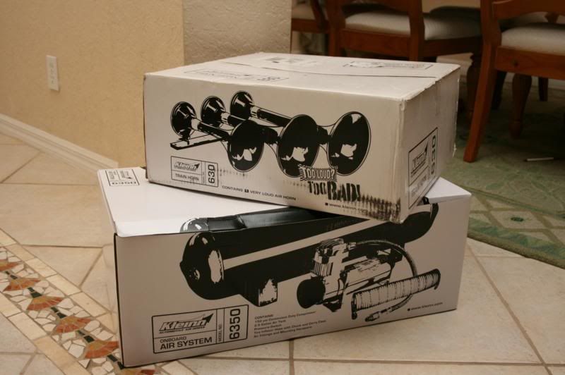
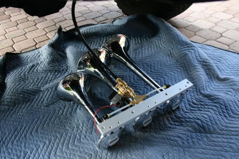
Here is what we will be installing today.
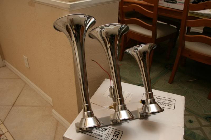
This the horn taken out of the box. It is made out of spun copper and is chrome plated.
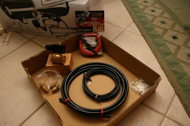
The rest of the contents of the horn package. There is an upgraded larger valve, some fittings, airline, hardware for installing the horn, and a wiring kit.
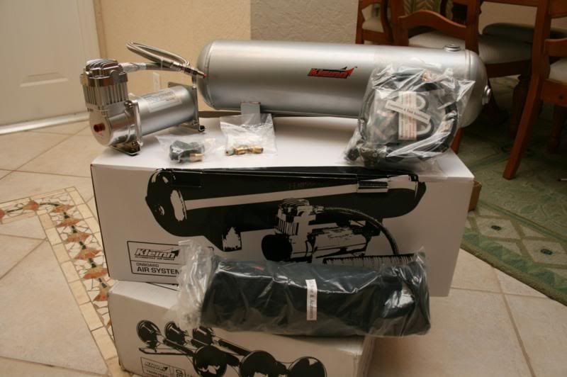
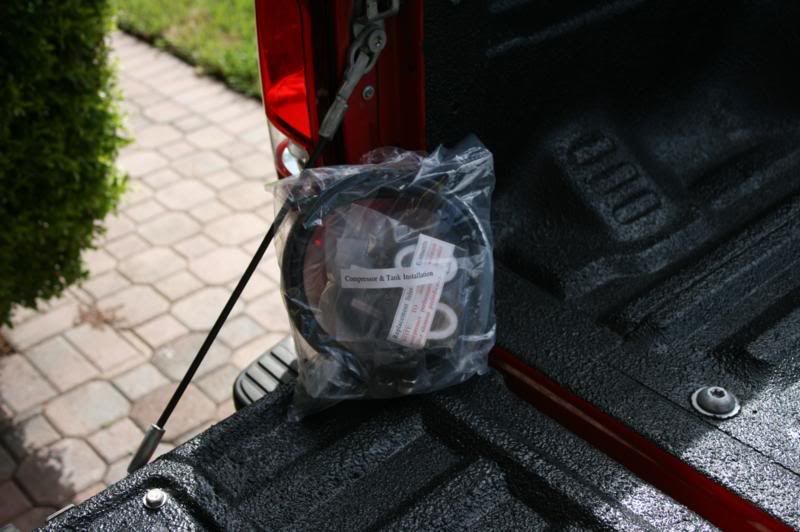
Here is the contents of the onboard air system box. There is a 2.5 gallon tank, 100% duty cycle compressor, pressure switch, fittings for the tank, hardware for mounting both the compressor and tank, remote intake snorkel kit, and a hose with tire chuck on the end.
The horns come with a smaller valve that is preinstalled. This will have to be removed to install the bigger upgraded valve.
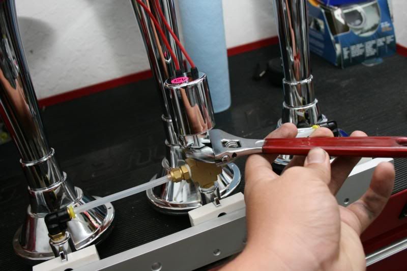
Now we are going to remove the valve. Take a wrench and unscrew it.
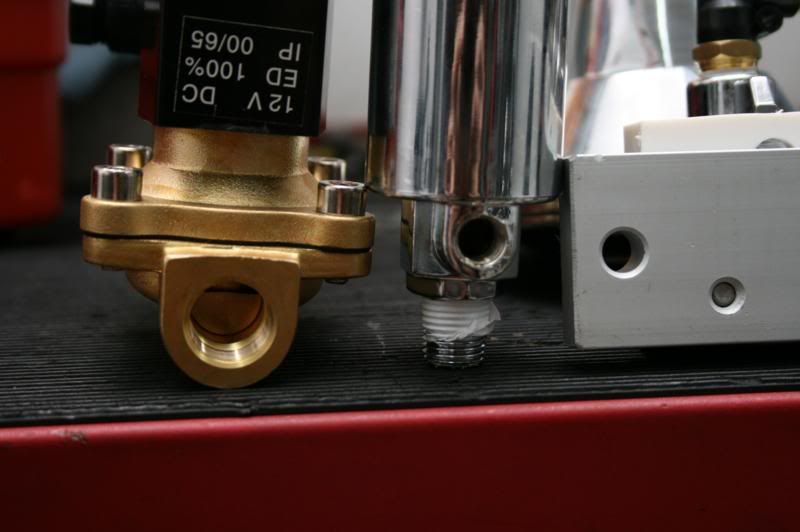
With the valve removed lets compare port sizes. Notice how much larger the ports are on the new valve. Much larger and will flow much more air, in turn maximizing the volume.
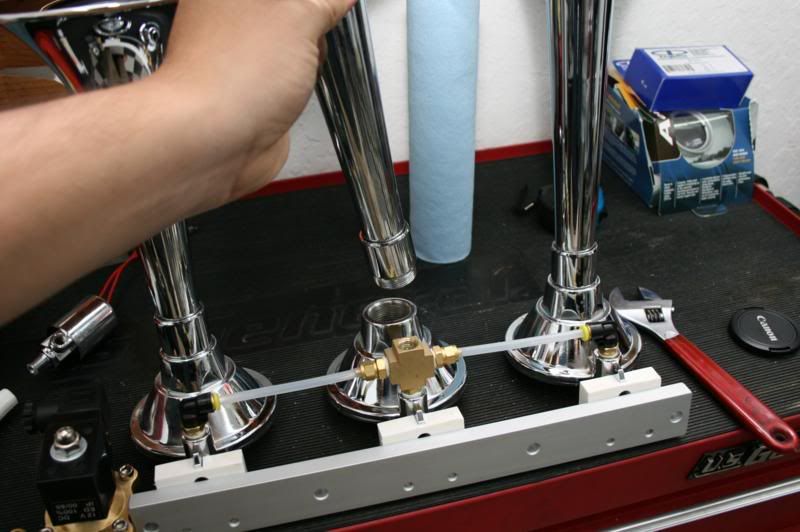
Size the new valve is much larger than the old one, you won't be able to install it without removing the middle trumpet. It is simple to remove, simply unscrew it and place it out of the way.
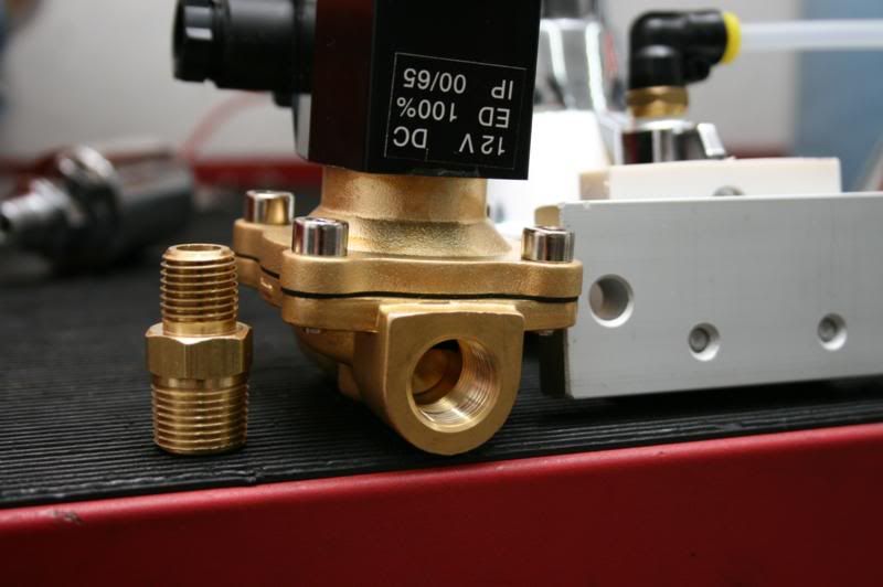
We need to install the included adapter fitting to install the valve.
Now install the fitting making sure to use a thread sealant such as the included teflon tape, or a liquid thread sealant. The valve is directional and has an arrow on the side of it. Since the airflow is going to the horns, this arrow needs to be pointing towards the horns. The fitting goes on the end that is toward the horns.

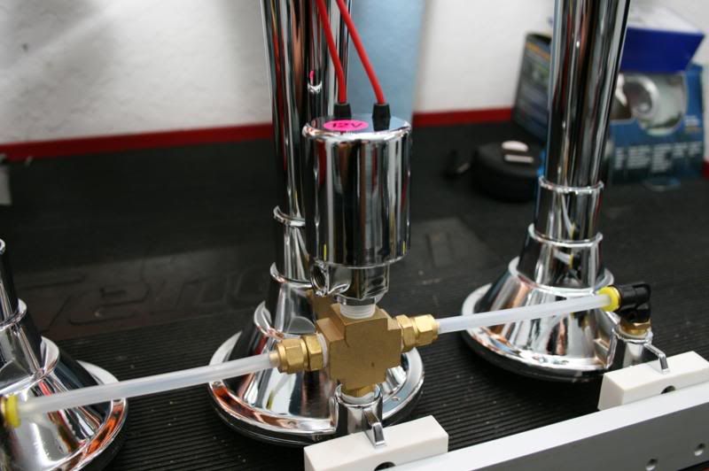
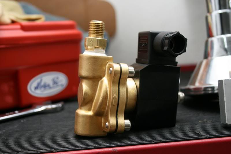
Install the valve, once again being sure to use thread sealant. You can now put the center trumpet back on also.
Now we need to put the other fitting on the valve so that the airline can connect to it.
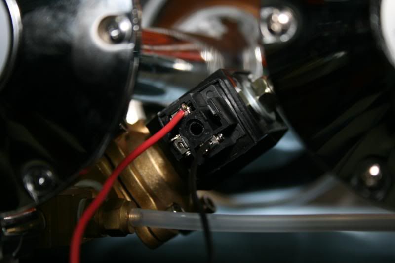
Now that the fittings are installed, we are going to put power leads on the valve. There are small phillips head screws that need to be loosened, then you install the stripped wire end, and snug the screw down. You will see that there are three spots that a wire can be installed. Do not use the middle one, only the sides. Polarity doesn't matter.
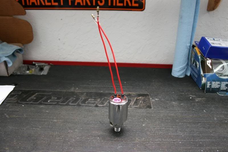
If you have a valve like the one that we removed, wiring is easy too.
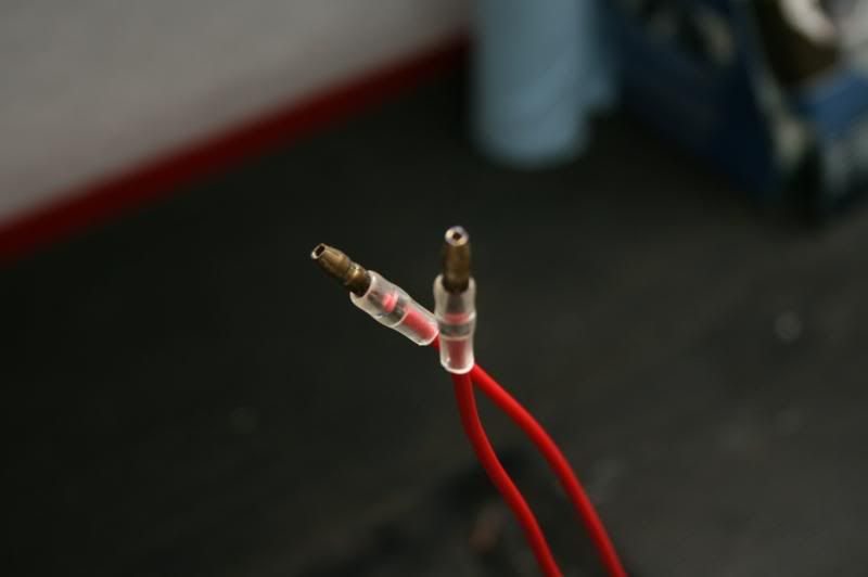
Just connect these leads. One to power and one to ground, polarity doesn't matter.
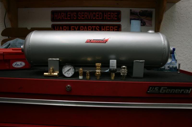
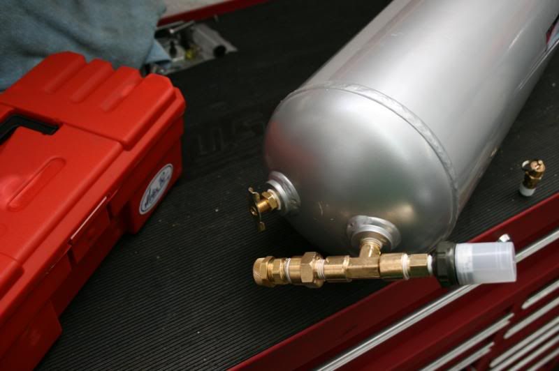
Now that we are done with the horn, it's time to move on to the air tank. All of these fittings will be installed. For this install I have added a pressure gauge which I bought at a local hardware store. You will also notice there is a T junction. Since I am adding the pressure gauge there needs to be one more port on the tank. Make sure to use thread sealant on every fitting.
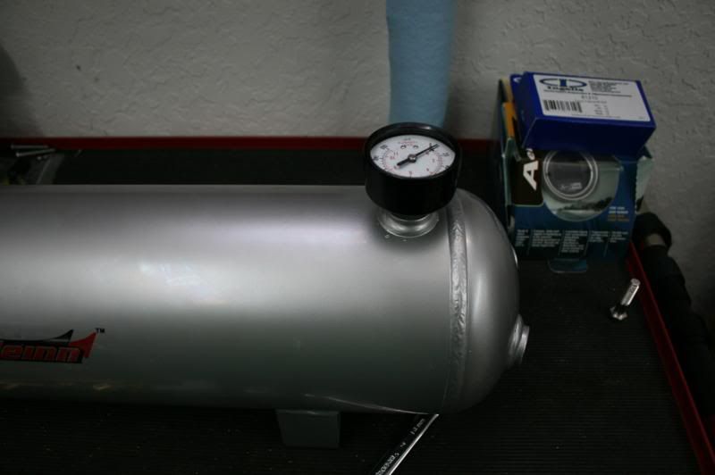
The first thing we are going to install is the pressure gauge. For this particular install the tank is going to be mounted to a vertical surface. If you were installing this onto a flat horizontal surface you would want to use this port for the safety pressure release valve.
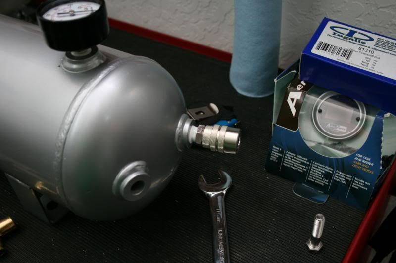
Next we will install the quick connect fitting for the air hose.
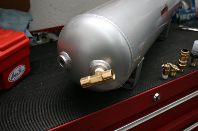
From here we will go to the other side and install the T junction.
Now install the pressure switch. The fitting on the switch is 1/8" NPT were as everything else is 1/4" NPT. So you need to make sure you install the included adapter fitting. Also, it is very important that the pressure switch is mounted towards the top of the tank. Water will get into the tank slowly through the humidity in the air, and water can ruin the pressure switch. So mount the switch somewhere where it won't be easy for water to come in contact with the switch.
Next install the airline fitting so we can connect the tank to the horns.
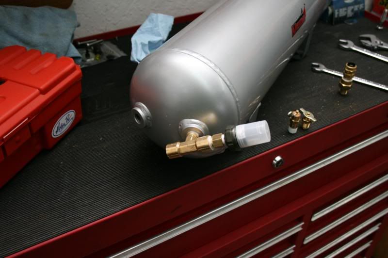
Now we install the drain cock. It is a good idea to drain the tank about once every 2-3 weeks.
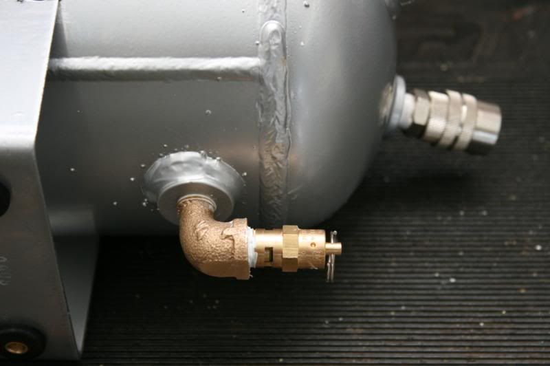
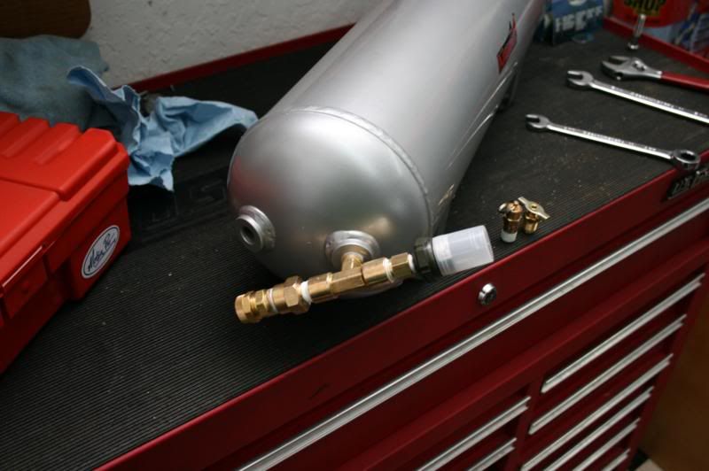
The last thing we will install is the safety pressure release. The fitting sticks out too far, so if you are installing your tank the same way as me you will need to use a 90* fitting. If you are installing your tank to a horizontal surface you need to use this port for the drain cock since it would be the only low point.
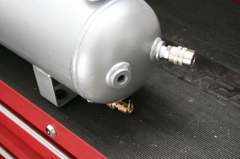
You may have noticed that there is one port that nothing was installed. This port is going to be used for the compressor leader hose.
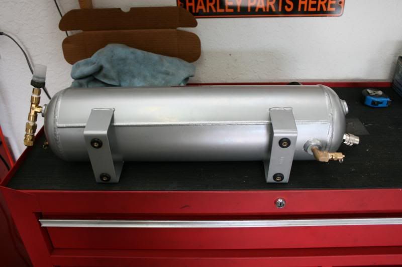
Now install the included rubber bushings in the holes on the feet of the tank. They have a brass insert in them so that they don't compress much when you tighten down the bolts. Installation of the bushings is much easier if you take the brass inserts out.
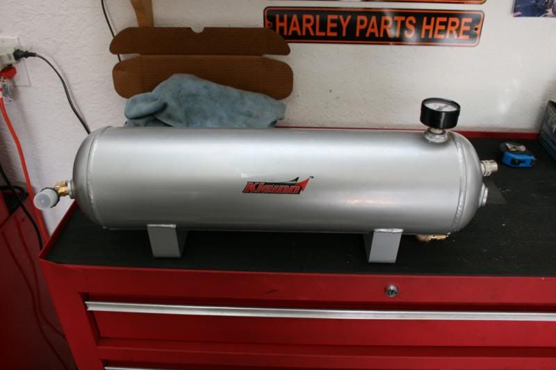
Tank is done.

Now place the tank and compressor next to each other so you can get an idea of how the mounting is going to be.
Once you figure out where you want the tank, mark and drill the holes so you can mount it. Use the included hardware. Then mount the tank.
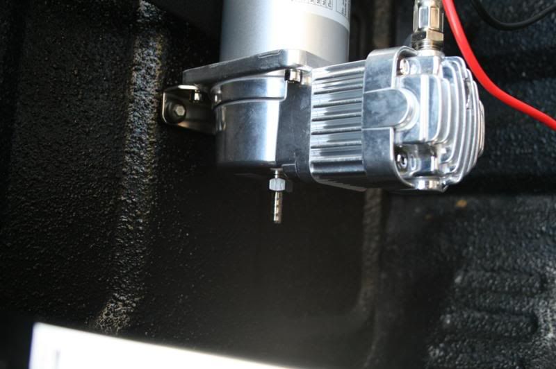
Mount the compressor in a spot that gets minimal dust and water. This compressor is sealed so the mounting options are much greater. If your compressor is a cheaper non-sealed one you will need to make sure it is mounted somewhere that gets no dust and no moisture or the life of the compressor will decrease severely.
Connect the leader hose to the tank.
Now we need to install the intake for the compressor. For my install the compressor will be under a tonneau cover so I don't need a remote intake. But we will go over the installation of it anyway.
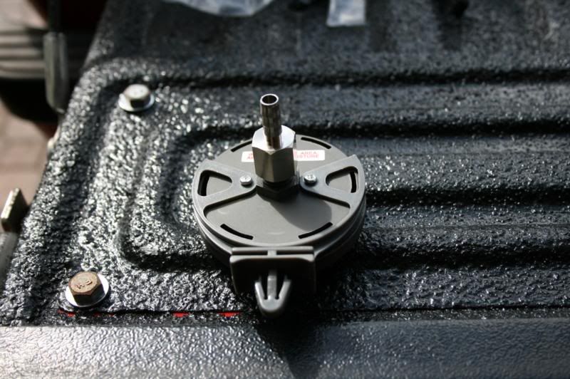
Install the fitting on the compressor.
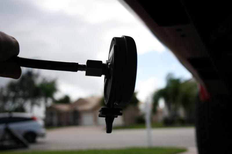
And the fitting on the airfilter housing.
Then connect the included air hose to the barbed fittings and route the line into the area inbetween the bed and the bedside.
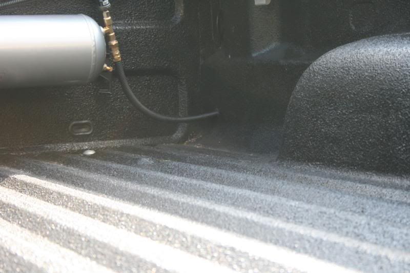
Next connect the 1/2" airline to the fitting on the tank. In this picture you can see that I also covered the airline with wire loom for some protecting against chaffing. I also drilled a hole in the bed to route the line.
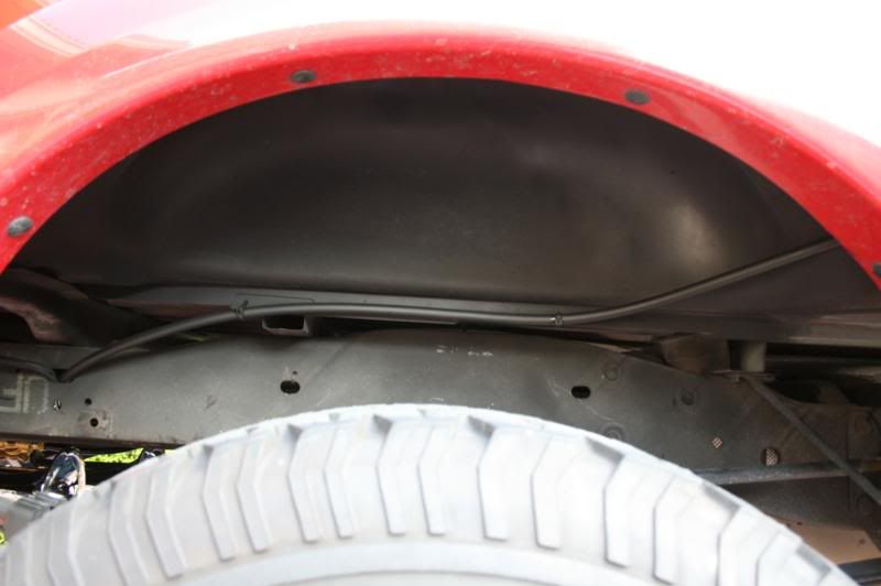
Route the airline along the frame. Since the exhaust is also on the same side as airline in this install, we will be routing the line on the outside of the frame to keep it away from heat.
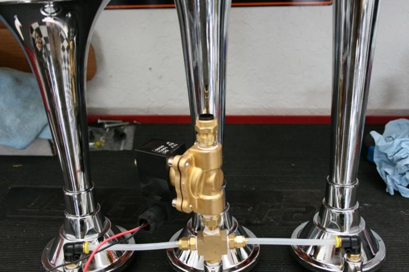
Now that you have your airline where the horn is going to be, connect it to the horn.
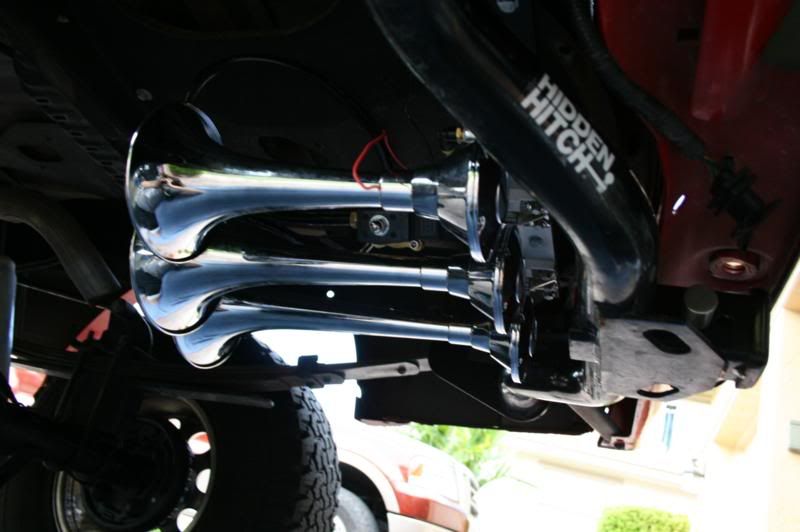
Mount the horn.
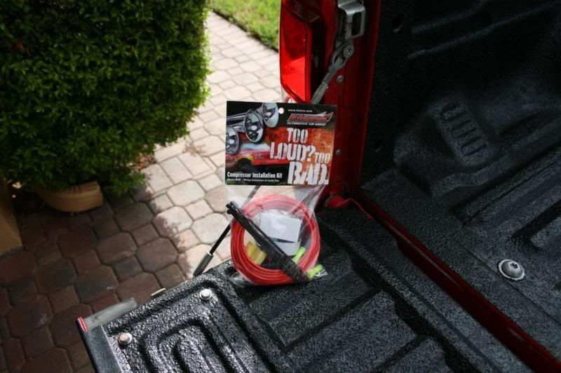
The only thing left to do now is wire everything up. Use the included wiring kit to do this. You will also need another switch or two and some more wire.
To make it easier I have made some wiring diagrams to use.
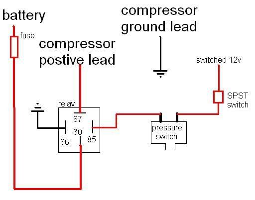
Here is a wiring diagram for the compressor/onboard air part of the system.
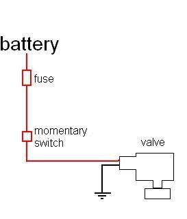
Here is how to wire the valve for the horn if you are using a separate momentary switch.
If you are using your stock horn button you need first determine how it works. If by pressing the button you are grounding the horn you need to wire it differently than if pressing the button connects the positive to the horn. Here is a diagram for each.
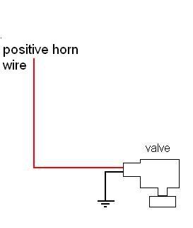
If the horn wire is positive.
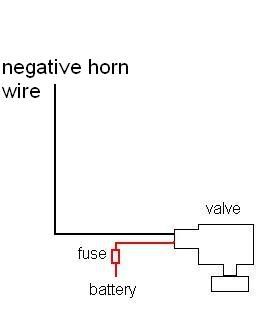
If the horn wire is a ground.
Now everything is wired and covered in wire loom.
Relay connected and mounted.
Horns wired and done.
Now that everything is done, here is a small video showing how the horns sound and showing the compressor filling the tank. The horns sound deeper and less high pitched in real life.
Here is what we will be installing today.
This the horn taken out of the box. It is made out of spun copper and is chrome plated.
The rest of the contents of the horn package. There is an upgraded larger valve, some fittings, airline, hardware for installing the horn, and a wiring kit.
Here is the contents of the onboard air system box. There is a 2.5 gallon tank, 100% duty cycle compressor, pressure switch, fittings for the tank, hardware for mounting both the compressor and tank, remote intake snorkel kit, and a hose with tire chuck on the end.
The horns come with a smaller valve that is preinstalled. This will have to be removed to install the bigger upgraded valve.
Now we are going to remove the valve. Take a wrench and unscrew it.
With the valve removed lets compare port sizes. Notice how much larger the ports are on the new valve. Much larger and will flow much more air, in turn maximizing the volume.
Size the new valve is much larger than the old one, you won't be able to install it without removing the middle trumpet. It is simple to remove, simply unscrew it and place it out of the way.
We need to install the included adapter fitting to install the valve.
Now install the fitting making sure to use a thread sealant such as the included teflon tape, or a liquid thread sealant. The valve is directional and has an arrow on the side of it. Since the airflow is going to the horns, this arrow needs to be pointing towards the horns. The fitting goes on the end that is toward the horns.
Install the valve, once again being sure to use thread sealant. You can now put the center trumpet back on also.
Now we need to put the other fitting on the valve so that the airline can connect to it.
Now that the fittings are installed, we are going to put power leads on the valve. There are small phillips head screws that need to be loosened, then you install the stripped wire end, and snug the screw down. You will see that there are three spots that a wire can be installed. Do not use the middle one, only the sides. Polarity doesn't matter.
If you have a valve like the one that we removed, wiring is easy too.
Just connect these leads. One to power and one to ground, polarity doesn't matter.
Now that we are done with the horn, it's time to move on to the air tank. All of these fittings will be installed. For this install I have added a pressure gauge which I bought at a local hardware store. You will also notice there is a T junction. Since I am adding the pressure gauge there needs to be one more port on the tank. Make sure to use thread sealant on every fitting.
The first thing we are going to install is the pressure gauge. For this particular install the tank is going to be mounted to a vertical surface. If you were installing this onto a flat horizontal surface you would want to use this port for the safety pressure release valve.
Next we will install the quick connect fitting for the air hose.
From here we will go to the other side and install the T junction.
Now install the pressure switch. The fitting on the switch is 1/8" NPT were as everything else is 1/4" NPT. So you need to make sure you install the included adapter fitting. Also, it is very important that the pressure switch is mounted towards the top of the tank. Water will get into the tank slowly through the humidity in the air, and water can ruin the pressure switch. So mount the switch somewhere where it won't be easy for water to come in contact with the switch.
Next install the airline fitting so we can connect the tank to the horns.
Now we install the drain cock. It is a good idea to drain the tank about once every 2-3 weeks.
The last thing we will install is the safety pressure release. The fitting sticks out too far, so if you are installing your tank the same way as me you will need to use a 90* fitting. If you are installing your tank to a horizontal surface you need to use this port for the drain cock since it would be the only low point.
You may have noticed that there is one port that nothing was installed. This port is going to be used for the compressor leader hose.
Now install the included rubber bushings in the holes on the feet of the tank. They have a brass insert in them so that they don't compress much when you tighten down the bolts. Installation of the bushings is much easier if you take the brass inserts out.
Tank is done.
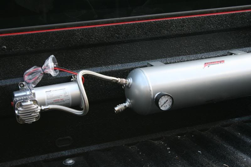
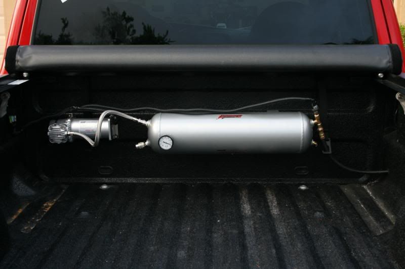
Now place the tank and compressor next to each other so you can get an idea of how the mounting is going to be.
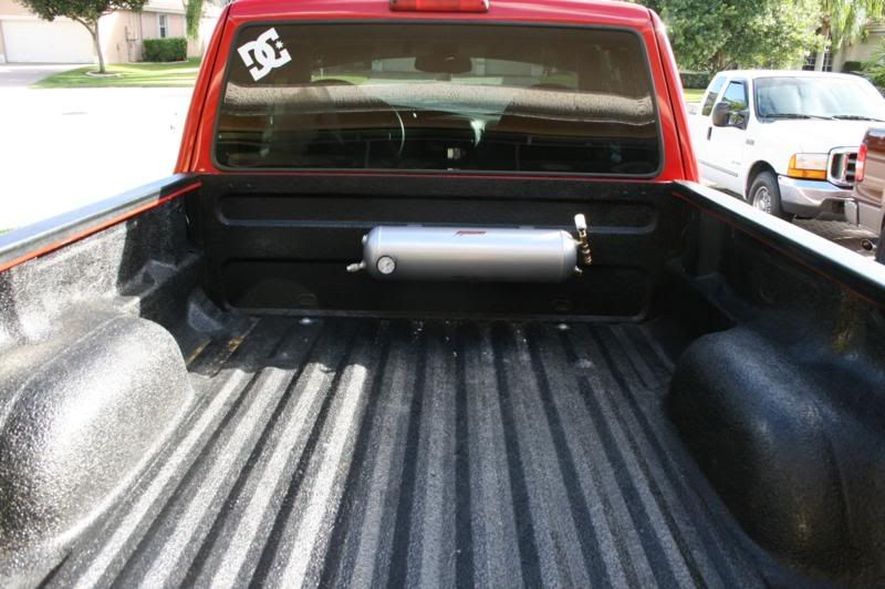
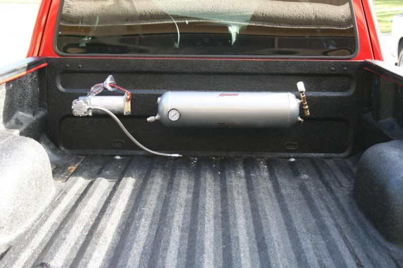
Once you figure out where you want the tank, mark and drill the holes so you can mount it. Use the included hardware. Then mount the tank.
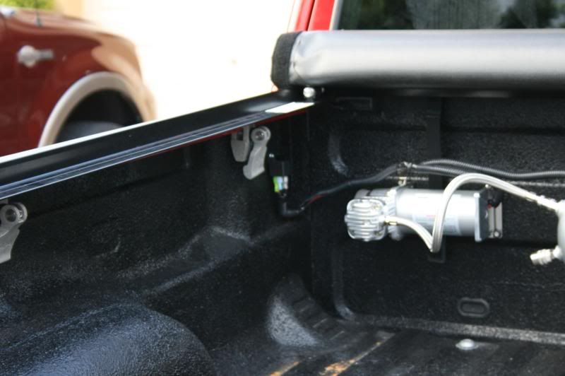
Mount the compressor in a spot that gets minimal dust and water. This compressor is sealed so the mounting options are much greater. If your compressor is a cheaper non-sealed one you will need to make sure it is mounted somewhere that gets no dust and no moisture or the life of the compressor will decrease severely.
Connect the leader hose to the tank.
Now we need to install the intake for the compressor. For my install the compressor will be under a tonneau cover so I don't need a remote intake. But we will go over the installation of it anyway.
Install the fitting on the compressor.
And the fitting on the airfilter housing.
Then connect the included air hose to the barbed fittings and route the line into the area inbetween the bed and the bedside.
Next connect the 1/2" airline to the fitting on the tank. In this picture you can see that I also covered the airline with wire loom for some protecting against chaffing. I also drilled a hole in the bed to route the line.
Route the airline along the frame. Since the exhaust is also on the same side as airline in this install, we will be routing the line on the outside of the frame to keep it away from heat.
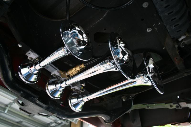
Now that you have your airline where the horn is going to be, connect it to the horn.
Mount the horn.
The only thing left to do now is wire everything up. Use the included wiring kit to do this. You will also need another switch or two and some more wire.
To make it easier I have made some wiring diagrams to use.
Here is a wiring diagram for the compressor/onboard air part of the system.
Here is how to wire the valve for the horn if you are using a separate momentary switch.
If you are using your stock horn button you need first determine how it works. If by pressing the button you are grounding the horn you need to wire it differently than if pressing the button connects the positive to the horn. Here is a diagram for each.
If the horn wire is positive.
If the horn wire is a ground.
Now everything is wired and covered in wire loom.
Relay connected and mounted.
Horns wired and done.
Now that everything is done, here is a small video showing how the horns sound and showing the compressor filling the tank. The horns sound deeper and less high pitched in real life.


