|
|
||||||||||||||
|
|
||||||||||||||
|
|
|
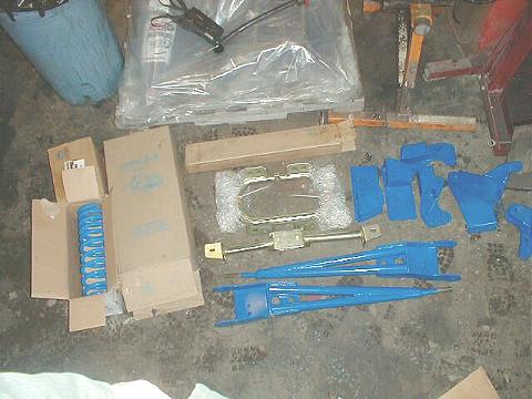
James Duff Stage 2 Lift Install By William Wills As promised in the last issue of TRS Magazine, we are starting our build-up of the TRS project truck. First in line, naturally, is the suspension lift. If you’ll remember back to the first issue, we discussed my need for more wheel travel while maintaining the strength of the suspension. This truck is no toy, it has to survive a pounding. I picked the Duff Stage 2 suspension kit which came with add-a-leafs to raise the rear.
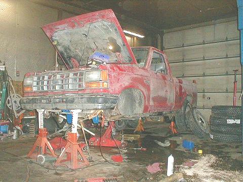
Early one Friday morning, I piled the suspension parts into my truck, along with my 4.10 Yukon gears and headed out on a 400 mile drive to Steinbinder’s Service in Negley, Ohio where Jim Oaks and I were to install the lift and shoot the story. While we did the lift John Steinbinder was on hand to do the gear set-up and offered a little pro bono technical assistance when we became bogged down. Fortunately, though I had blasted the bottom of the truck with a pressure washer the day before, it snowed the entire drive. Instead of just a simple lift install, be now had the opportunity for a true character-building experience. We ran the slushy, salt encrusted, ice packed truck into the warm shop and put it up on stands; we would spend 36 hours over the next 2 days mopping up the freezing brine with our cover-alls.
Putting the stands near the ends of the frame keeps them out of the way while working on the suspension. With the suspension hanging freely on both ends we burped the lugnuts off with the impact and removed the tires. The tires out of the way, we started on the front end removing the lock-outs, axle spacers, retaining rings, wheel bearing adjuster and locknuts. We knocked the pins out of the brake calipers and swung them forward to wire them up away from the suspension parts. After removing the spindle nuts, a slide hammer made quick work of jerking off the spindles. With the spindles off we removed the axle shafts by simply pulling them out, remembering to remove one of the Keystone clamps from the boot on the right axle. Next we removed the nuts from the tie-rod ends and tapped the ends out of the knuckles. With the ends of the axle beams free, we removed the bolts from the axle pivots and the nuts from the ends of the radius arms and got a jack under the beams to facilitate removing them. Removing them is a simple matter of pulling the axle down out of the pivot and sliding it forward out of the radius arm bracket. With the axle assemblies out we were ready to dismantle them.
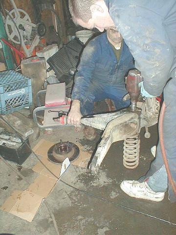
A huge impact wrench is a big plus here and we had a 3/4" drive unit available. With a deep socket and an extension we reached down through the coil springs and ran the nuts off, removing the retaining washer, spring and spring seat. Now it gets a little tougher. The bottom bolts are easily removed with a big impact but if you are using a breaker bar its best to remove these with the axle still bolted to the truck. The top bolts are a different story because they are actually long studs. Too long, in fact, for even a deep-well socket. For these we used a combination wrench with a cheater on the end and a lot of heat. After the bolts were out we knocked off the radius arms and removed the differential from the left beam. After handing the differential over to the shop for the gear set-up we got to work getting the factory drop brackets out and replacing them with the new brackets.
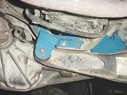
Installing the new left bracket (mounted on the right side) was a simple matter of unbolting the old and bolting on the new in its place. The only change in its mounting from the factory bracket was that the Duff bracket has a tab that wraps around to the outside of the frame and bolts through an existing hole: one that it will share with the new shock hoop. The right drop bracket (mounted on the left side) is a bit harder to install.
The factory bracket is connected to the engine crossover with large rivets. There isn’t a lot of room to drill here so a long appointment with the angle grinder is usually required to get these rivets off. Fortunately, we had a torch on hand and it was only a matter of minutes before the rivet heads were laying smoking on the floor. With the heads off, we ground the remaining metal slag off of the rivet and then knocked them through with a punch. Then we installed the new bracket with the provided hardware. The gear set-up was nearing completion at this point so we decided to turn our attention to the new transmission mount in preparation to reinstalling the front axle beams.
The Duff transmission mount provides lateral support for their extended radius arm brackets. The brackets themselves are bolted through existing holes in the sides of the frame. Once the brackets are bolted in, new holes are drilled through the bracket into the top of the frame and the transmission mount is bolted through these new holes. When the new mount was in place and the differential handed back to us, we turned our attention to reassembling the axle beams.
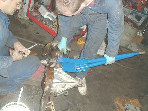
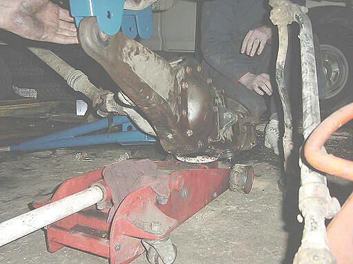
With the left beam cleaned up and ready for the differential, we ran a bead of silicon around the seam, allowed it to set-up, and then dropped the differential straight down onto the beam and installed the bolts. We did not replace the pinch-bolt onto the carrier because it makes it difficult to remove the differential housing without pulling off the radius arm. With the housing bolts torqued we turned out attention to the installation of the new extended radius arms.
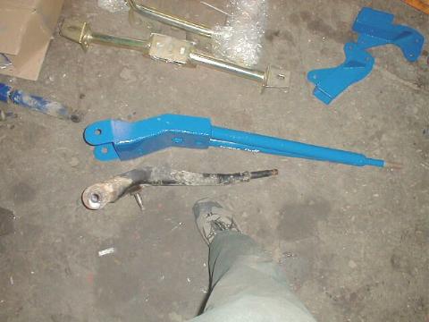
Saying that the new radius arms were difficult to get on is an understatement: they were a bear. The method that ended up working best for this was clamping the axle beam in a huge vise, inserting one of the bolts and running it in a few turns. Then we had someone lift up on the radius arm and another person to pry the top of the arm over while the third got the bolt started. It took a while but we got it. Just don’t tighten the bolts until the radius arms and axle pivot bolts are lined up back on the truck. With the radius arms on the beams we were ready to get the assembled beams back on the truck.
The beams are installed just as they were removed. We put a jack under them, assembled the bushings on the ends of the radius arms, pushed the radius arms into the new brackets and then swung the axle ends back into the pivots. The outer radius arm bushing washer were installed and then the nuts were torqued on. That done, we torqued the axle pivot bolts and then tightened the bolts that hold the radius arms onto the axle beams.
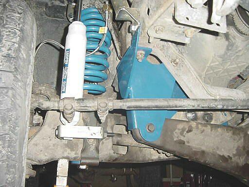
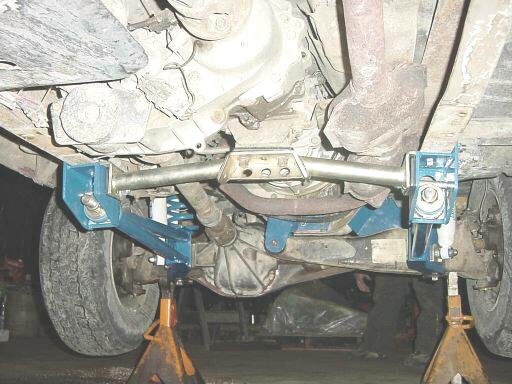
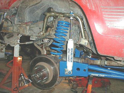
With the top stud tightened we dropped spring seat, spring and washer down on the stud and tightened the nuts. That done, we jacked up each axle beam and popped the springs up into their top mounts. Now we were ready to tackle the Duff shock hoops. The dual shock kit takes a little figuring to get it on. The top of the shocks are fastened to a hoop that fits around behind the coil bucket and bolts to the frame on either side of it. The fronts of the hoops using existing holes: one shares a hole with the new axle drop bracket and the other with the steering box. The backs of the hoops require holes to be drilled. Once the hoops were in place the bottom shock mounts had to be fitted. The rear shock mounts were bolted to the radius arms. The front mounts utilized the sway bar bracket and required a bit of thinking to get them together. With the front lift on it was obvious that we could not let the suspension droop without stretching out the stock brake hoses so we broke out the new set and went about installing them.
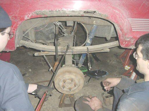
The brake hoses are fastened to the top of the coil buckets by clips that have to be pushed out and then the hoses unscrewed from the fittings. It’s a tough job and we had to remove the air box and the battery to be able to get at the right side. The new set is held on with a large nut and was much easier to deal with. Once the lines were on we gravity-bled the front brakes and then reassembled the axle ends. Now it was time to move on the the rear suspension. This particular Duff kit uses a short, thick leaf added to each rear pack. We rested the rear axle housing on stands and removed the U-bolts with a deep socket. After that we were able to lower the axle housing away from the springs, which were still held together by the center-bolt. The top clamp and spacer block also came free with the removal of the U-bolts. We used the angle grinder to remove the heads on the center-bolts and then separated the springs. We installed the new spring above the load-stopper spring and using large C-clamps, squeezed the pack tightly together. My truck is worked hard and this became evident when we were clamping the springs back together. The old springs have lost quite a bit of curvature along the center third of their length and clamping on the new spring forced them back into shape. Eventually I expect they will find a happy existence somewhere in between. With the pack tightened together, we verified that the center holes were aligned and then ran the new center-bolt through the springs and tightened it down. Next, we cut all but the last two threads from the center bolt and then mashed those down with a hammer to prevent their loosening when the springs shift around. We now jacked the axle housing back up to the springs, replaced the blocks and top clamps and installed the new U-bolts. The big C-clamps really came in handy here as we were able to use them to squeeze the U-bolts together in order to line them up more easily. With the bolts on we partially tightened the nuts and then tapped the bottoms in line with a hammer before torquing them.
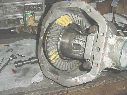
The last things to be done were replacing the rear shocks and having the gears installed in the rear axle. The rear shocks are simply longer replacements for the stock ones and require no thought. Held on by nuts and studs on the top and nuts and bolts on the bottoms we had them replaced in moments. With the shocks done, we set about getting the rear axle ready for the shop to do the gears. To drain the rear axle we removed the cover bolts and then pried it loose to let the fluid drain. Once the fluid was out, we pulled the cover free and cleaned the housing and cover while John did the gear set-up and rebuilt the axle. Then the axle cover went back on and we filled the front and rear differentials with gear oil. The only complaints we had with the Duff kit were that the instructions are very incomplete and that they skimped on the length of the U-bolts. We spent a good deal of time trying to figure out how the shock hoops went on and even after I got it home, I ended up removing them again and changing a few things around. There were no instructions included for the radius arm/ transmission crossover. Considering the amount of time they must have spent engineering this suspension kit, how much more time would it have added to include decent instructions? As to the rear U-bolts: the darn things were simply too short. Through huge effort we were able to get them on far enough to hold, but there is absolutely no thread sticking up past the nuts. It is likely that since my truck has the GVW package on it my spring pack is a little thicker than Duff was counting on, but it would have been easy for them to have made the U-bolts an inch longer. This would make assembling them much more easy as well.
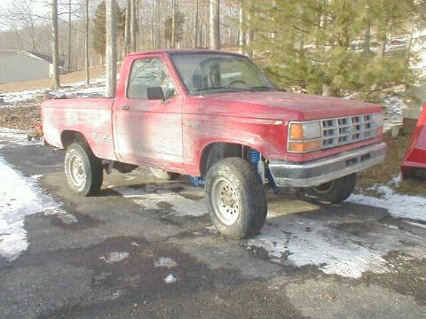
After we finished admiring our handy work, I jumped in my truck at 3AM Sunday morning and drove home. It snowed the whole way home. The truck pulled a little and I was a little anxious about driving 400 miles across Ohio and half of Indiana on my new gears. But they were perfectly quiet and the gear oil was clear when I changed it. Steinbinder’s Service does good work.
So the first step in the TRS Project Truck is complete. Next issue we will discuss tire selection, doing the initial alignment and then we will take the TRS Project Truck out for a real-world drive to compare it to the previously measured stock wheel travel. Stay tuned.~
|
|
|