Problem:
2000 Ranger 4×4. 4×4 will not engage. Green indicator light on switch will not illuminate. 4×4 high and low lights in dash will flash 4 or 5 times when key is first turned on but they do go off. Turn the 4×4 switch on and nothing happens, no lights, nothing. The motor on t-case never moves. I removed the motor and manually engaged 4×4 and it works fine. I can take a test light and get no power at the motor or the dash mounted switch. I can ground my test light and get nothingat the switch, but I can connect the lead to a power source and get a ground at 3 of the wires on the switch. The white wire with green stripe is open both ways I check it. The fuse is good and I even replaced the module with a new unit and that didn’t help. I’m at the end of my rope, please help! Thanks
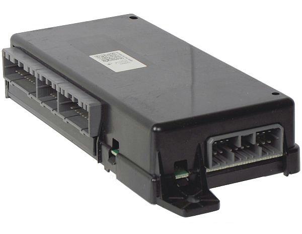
Trouble code: P1808-P1812-P1815-P1820. Replaced module#YL5Z-14B205-EA
Trouble Shooting Procedures
Since the 1995-2000 transfer case shift control module is part of the GEM, you can use a code reader (scan tool) to get the trouble codes.
The codes for this problem were identified as:
- P1808 4WD Low Indicator Circuit Open/Short To Ground
- P1812 4WD Mode Select Switch Circuit Open
- P1815 4WD Mode Select Switch Circuit Short To Ground
- P1820 Transfer Case LO/HI Shift Relay Circuit Open/Short To Gnd
For the complete list of OBD-II Trouble Codes, click HERE.
Here are the troubleshooting procedures for the codes. Symptoms indicate a more likely wiring fault somewhere. Check for bad connectors or broken/damaged wires/harness.
TEST C: 4X4 HIGH &/OR 4X4 LOW INDICATOR DOES NOT OPERATE PROPERLY
GEM CONNECTOR IDENTIFICATION
Connector No. = Description
C221 = 26-Pin
C223 = 22-Pin
C224 = 18-Pin
1. Check Ignition States; Monitor GEM PID IGN_GEM
Turn ignition off. Connect NGS tester. Depress clutch pedal, if applicable. Monitor GEM PID Ignition Switch Status (IGN_GEM) while turning ignition switch through RUN, OFF and ACC positions. If values agree, go to next step. If values do not agree, diagnose ignition
switch and circuits.
2. Retrieve DTCs
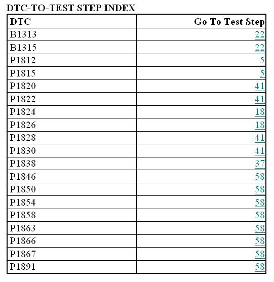
Retrieve and document continuous DTCs. Clear continuous DTCs. Retrieve on-demand DTCs. If DTCs are retrieved, go to appropriate step(s). See DTC-TO-TEST STEP INDEX table. If DTC B1342 is present, replace GEM. Clear DTCs and retest. If no DTCs are retrieved, go to next step.
DTC-TO-TEST STEP INDEX
DTC P1804 Go To Test Step 3
DTC P1806 Go To Test Step 3
DTC P1808 Go To Test Step 3
DTC P1810 Go To Test Step 3
3. Verify Inoperative Indicator Light
If 4X4 HIGH indicator light is not operating, go to next step. If 4X4 LOW indicator light is not operating, go to step 9.
4. Check GEM PID 4X4 HIGH Indicator Light
Monitor GEM PID 4WDHIGH while triggering GEM active command HIGH LAMP on, and then off. If 4X4 HIGH indicator light illuminates, and then turns off, go to next step. If indicator light does not illuminate, and then turn off, and PID displays ON-B, go to step 12. If PID displays OFFO-G, go to next step.
5. Check GEM PID 4X4 LOW Indicator Light
Monitor GEM PID 4WDLOW while triggering GEM active command LOW LAMP on, and then off. If 4X4 LOW indicator light illuminates, and then turns off, system is operating correctly. Go to TEST A. If indicator light does not illuminate, and then turn off, and scan tool displays ON-B-, go to step 12. If scan tool displays OFFO-G, go to next step.
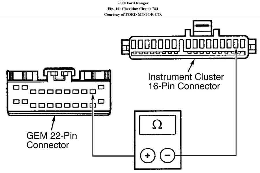
6. Check Circuit 784 (Light Blue/Black Wire) For Open
Turn ignition off. Disconnect GEM 22-pin connector and instrument cluster. See Fig. 2. Using ohmmeter, measure resistance of Light Blue/Black wire between terminal No. 2 at instrument cluster harness connector and terminal No. 10 at GEM harness connector. See Fig. 10. If resistance is less than 5 ohms, go to next step. If resistance is not less than 5 ohms, repair open in Light Blue/Black wire. Clear DTCs and retest system.
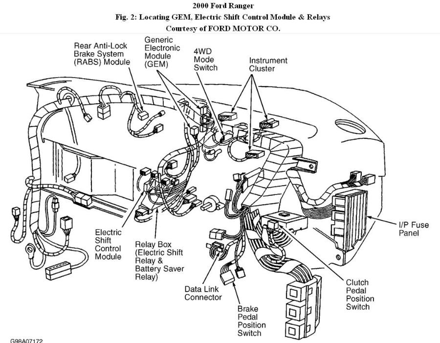
(Figure 2)
(Figure 10)
7. Check Circuit 784 (Light Blue/Black Wire) For Short To Ground
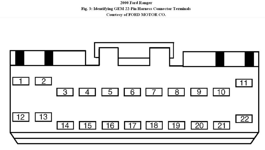
Using ohmmeter, measure resistance of Light Blue/Black wire between ground and terminal No. 10 at GEM 22-pin harness connector. See Fig. 3. If resistance is more than 10 k/ohms, reconnect instrument cluster connector, and then go to next step. If resistance is not more than 10 k/ohms, repair short to ground in Light Blue/Black wire. Clear DTCs and retest system.
(Figure 3)
8. Check Instrument Cluster
Turn ignition on, engine off. Connect jumper wire between ground and terminal No. 10 on GEM 22-pin harness connector. If 4X4 LOW indicator light illuminates, go to next step. If 4X4 LOW indicator light does not illuminate, check condition of indicator light bulb. If bulb is okay, repair or replace instrument cluster printed circuit. Clear DTCs and retest system.
9. Check Circuit 783 (Gray Wire) For Open
Turn ignition off. Disconnect instrument cluster connector C214. See Fig. 2. Using ohmmeter, measure resistance of Gray wire between terminal No. 3 at instrument cluster harness connector and terminal No. 14 at GEM 22-pin harness connector. If resistance is less than 5 ohms, go to next step. If resistance is not less than 5 ohms, repair open in Gray wire. Clear DTCs and retest system.
10. Check Circuit 783 (Gray Wire) For Short To Ground
Using ohmmeter, measure resistance of Gray wire between ground and terminal No. 14 at GEM 22-pin harness connector. See Fig. 3. If resistance is more than 10 k/ohms, go to next step. If resistance is not more than 10 k/ohms, repair short to ground in Gray wire. Clear DTCs and retest system.
11. Check Instrument Cluster
Turn ignition on, engine off. Connect jumper wire between ground and terminal No. 14 on GEM 22-pin harness connector. See Fig. 3. If 4X4 HIGH indicator light illuminates, replace GEM. Clear DTCs and retest system. If 4X4 HIGH indicator light does not illuminate, check condition of indicator bulbs. If bulbs are okay, repair or replace instrument cluster printed circuit. Clear DTCs and retest system.
12. Check Circuit 784 (Light Blue/Black Wire) For Short To Voltage
Turn ignition off. Disconnect GEM 22-pin harness connector and instrument cluster connector C214. Turn ignition on, engine off. Using DVOM, measure voltage on Light Blue/Black wire between ground and terminal No. 10 at GEM 22-pin harness connector. If voltage is more than 10 volts, repair short to voltage in Light Blue/Black wire. Clear DTCs and retest system. If voltage is 10 not more than volts, go to next step.
13. Check Circuit 783 (Gray Wire) For Short To Voltage
Using DVOM, check for voltage on Gray wire between ground and terminal No. 14 on GEM 22-pin harness connector. See Fig. 3. If voltage is present, repair short to voltage in Gray wire. Clear DTCs and retest system. If voltage is not present, go to next step.
14. Check Instrument Cluster
Monitor GEM PIDs 4WDHIGH and 4WDLOW while triggering GEM active commands LOW LAMP and HIGH LAMP off. If PIDs indicate OFFO-G, check condition of bulbs. If bulbs are okay, repair or replace instrument cluster printed circuit. Clear DTCs and retest system. If PIDs do not indicate OFFO-G, replace GEM. Clear DTCs and retest system.
TEST A: VEHICLE DOES NOT SHIFT BETWEEN 2WD & 4WD MODES PROPERLY
1. Check Ignition States; Monitor GEM PID IGN_GEM
Turn ignition off. Connect NGS tester. Depress clutch pedal, if applicable. Monitor GEM PID Ignition Switch Status (IGN_GEM) while turning ignition switch through RUN, OFF and ACC positions. If values agree, go to next step. If values do not agree, diagnose ignition switch and circuits.
NOTE: In next step, note that DTCs P1838 and P1866 require clearing GEM Keep Alive Memory (KAM) after repairs have been completed. NGS tester will not clear these DTCs. Disconnect and reconnect battery to clear these DTCs.
2. Retrieve DTCs
Retrieve and document continuous DTCs. Clear continuous DTCs. Perform GEM self-test. Retrieve DTCs. If DTCs are retrieved, go to appropriate test step(s). See DTC-TO-TEST STEP INDEX table. If DTC B1342 is retrieved, replace GEM, clear DTCs, and retest. If no DTCs are retrieved, go to next step.
3. Check 4X4 HIGH Indicator Light
Trigger GEM active command HIGH LAMP on, and then off. If 4X4 HIGH indicator light illuminates, and then turns off, go to next step. If indicator light does not illuminate, and then turn off, go to TEST C.
4. Check 4X4 LOW Indicator Light
Trigger GEM active command LOW LAMP on, and then off. If 4X4 LOW indicator light illuminates, and then turns off, go to next step. If indicator light does not illuminate, and then turn off, go to TEST C.
5. Check 4X4 Mode Switch
Turn ignition on, engine off. Monitor GEM PID 4WD_SW. Place mode switch in 2WD position. If PID indicates 2WD, go to next step. If PID does not indicate 2WD, go to step 8. If PID indicates OFFO-G, go to step 14.
6. Check 4X4 Mode Switch
Monitor GEM PID 4WD_SW. Place mode switch in 4X4 HIGH position. If PID indicates 4WD HIGH, go to next step. If PID does not indicate 4WD HIGH, go to step 8.
7. Check 4X4 Mode Switch
Monitor GEM PID 4WD_SW. Place mode switch in 4X4 LOW position. If PID indicates 4WD LOW, go to step 16. If PID does not indicate 4WD LOW, go to next step. If PID indicates OFFO-G, go to step 14.
8. Check 4X4 Mode Switch In 2WD Position
Turn ignition off. Disconnect 4X4 mode switch connector. Place mode switch in 2WD position. Using ohmmeter, measure resistance between center 2 terminals (No. 2 and 3) of mode switch. If resistance is 3700-4100 ohms, go to next step. If resistance is not 3700-4100 ohms, replace mode switch. Clear DTCs and retest system.
9. Check 4X4 Mode Switch In 4X4 HIGH Position
Place mode switch in 4X4 HIGH position. Measure resistance between center 2 terminals (No. 2 and 3) of mode switch. If resistance is 1050-1150 ohms, go to next step. If resistance is not 1050-1150 ohms, replace mode switch. Clear DTCs and retest system.
10. Check 4X4 Mode Switch In 4X4 LOW Position
Place mode switch in 4X4 LOW position. Measure resistance between center 2 terminals (No. 2 and 3) of mode switch. If resistance is 340-380 ohms, go to next step. If resistance is not 340-380 ohms, replace mode switch. Clear DTCs and retest system.
11. Check Circuit 465 (White/Light Blue Wire) For Open
Turn ignition off. Disconnect 4X4 mode switch connector. Disconnect GEM 22-pin connector. Measure resistance of White/Light Blue wire between terminal No. 3 on mode switch harness connector and terminal No. 8 on GEM harness connector. If resistance is less than 5 ohms, go to next step. If resistance is not less than 5 ohms, repair open in White/Light Blue wire. Clear DTCs and retest system.
12. Check Circuit 465 (White/Light Blue Wire) For Short To Voltage
Turn ignition on, engine off. Using DVOM, measure voltage between ground and terminal No. 3 (White/Light Blue wire) on 4X4 mode switch harness connector. If voltage is present, repair short to voltage in White/Light Blue wire. Clear DTCs and retest system. If voltage is not present, go to next step.
13. Check Circuit 465 (White/Light Blue Wire) For Short To Ground
Using ohmmeter, measure resistance between ground and terminal No. 3 on 4X4 mode switch harness connector. If resistance is more than 10 k/ohms, go to next step. If resistance is not more than 10 k/ohms, repair short in White/Light Blue wire. Clear DTCs and retest system.
14. Check Circuit 359 (Gray/Red Wire) For Open
Turn ignition off. Disconnect 4X4 mode switch connector. Disconnect GEM 26-pin connector. Measure resistance of Gray/Red wire between terminal No. 2 on mode switch harness connector and terminal No. 21 on GEM harness connector. If resistance is less than 5 ohms, go to next step. If resistance is not less than 5 ohms, repair open in Gray/Red wire. Clear DTCs and retest system.
15. Check Circuit 359 (Gray/Red Wire) For Short To Voltage
Turn ignition on, engine off. Using DVOM, measure voltage between ground and terminal No. 2 (Gray/Red wire) on 4X4 mode switch harness connector. If voltage is present, repair short to voltage in Gray/Red wire. Clear DTCs and retest system. If voltage is not present, replace GEM. Clear DTCs and retest system.
16. Check Front Drive Shaft Engagement
Start vehicle. Place shift lever in “D” position. Place mode switch in 4X4 HIGH and drive vehicle a short distance. Raise and support vehicle. With vehicle in Drive, front and rear drive shafts should both spin. If transfer case locks front drive shaft to rear drive shaft, go to next step. If front drive shaft does not engage, go to step 41. If 4WD engagement is prolonged, harsh or noisy, go to step 18.
17. Check Front Drive Shaft Disengagement
With vehicle lowered and engine running, turn 4WD mode switch to 2WD position. When 4X4 is disengaged, front drive shaft may spin due to viscous drag in transfer case, especially if cold. Drive a short distance in Reverse to disengage hubs. If only rear drive shaft spins, go to TEST E. If front and rear drive shaft are both spinning, front drive shaft is not working properly, go to step 41.
18. Check Electric Clutch Relay
Turn ignition off. Disconnect electric clutch relay. Relay is located in relay box behind center of dash. Test relay. If relay is okay, go to next step. If relay is not okay, replace relay. Clear DTCs and retest system.
19. Check Clutch Relay Coil Circuit
Turn ignition on, engine off. Trigger GEM active command SHIFT CLUTCH to ON. Monitor GEM PID 4WDELCL. If display is ON—, go to step 21. If display is ON-B-, go to next step.
20. Check Circuit 275 (Yellow Wire) For Short To Voltage
Turn ignition off. Disconnect electric clutch relay. Disconnect GEM 22-pin connector. See Fig. 2. Turn ignition on, engine off. Using DVOM, measure voltage between ground and terminal No. 1 (Yellow wire) on electric clutch relay socket. If voltage is present, repair short to voltage in Yellow wire. Clear DTCs and retest system. If voltage is not present, replace GEM. Clear DTCs and retest system.
21. Check Electric Shift Relay Coil Circuit
Trigger GEM active command SHIFT CLUTCH to OFF. Monitor GEM PID 4WDELCL. If display is OFF–, go to step 36. If display is OFFO-G, go to next step.
22. Check Battery Saver Relay
Turn ignition off. Disconnect battery saver relay. Relay is located in relay box behind center of dash. See Fig. 2. Test relay. If relay is okay, go to next step. If relay is not okay, replace relay. Clear DTCs and retest system.
23. Check Battery Saver Relay Coil Circuit
Reconnect battery saver relay. Turn ignition on, engine off. Trigger GEM active command BATT_SAVR to ON. Monitor GEM PID BATT_SAVR. If display is ON—, go to step 25. If display is ON-B-, go to next step.
24. Check Circuit 1005 (Violet/Orange Wire) For Short To Voltage
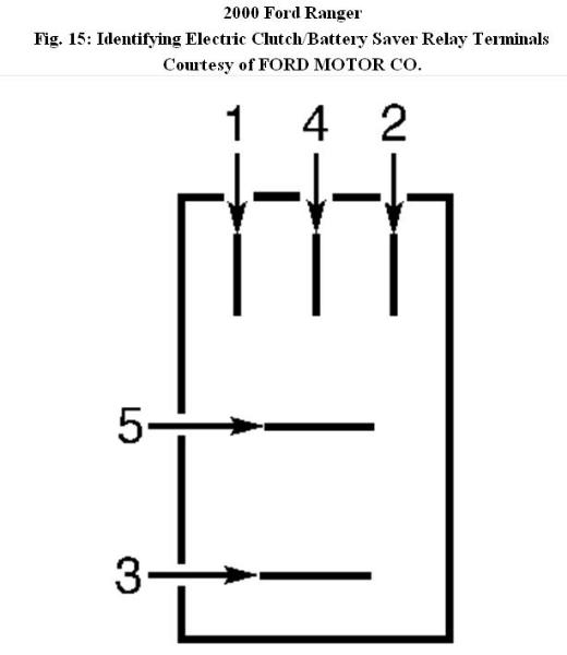
Turn ignition off. Disconnect battery saver relay. Disconnect GEM 18-pin connector. See Fig. 2. Turn ignition on, engine off. Using DVOM, measure voltage between ground and terminal No. 2 (Violet/Orange wire) on battery saver relay socket. See Fig. 15. If voltage is present, repair short to voltage in Violet/Orange wire. Clear DTCs and retest system. If voltage is not present, replace GEM. Clear DTCs and retest system.
(Figure 15)
25. Check Battery Saver Relay Coil Circuit
Trigger GEM active command BATT_SAVR to OFF. Monitor GEM PID BATT_SAVR. If display is OFF—, go to step 36. If display is OFFO-G, go to next step.
26. Measure Circuit 792 Voltage
Turn ignition off. Disconnect battery saver relay. See Fig. 2. Turn ignition on, engine off. Using DVOM, measure voltage on Tan/Yellow wire between ground and terminals No. 1 and 5 on battery saver relay socket. See Fig. 15. If voltage at both terminals is more than 10 volts, go to step 32. If voltage at either terminal is not more than 10 volts, go to next step.
27. Check Voltage Output From Fuse No. 26
Using DVOM, measure voltage on Tan/Yellow wire between ground and pin of fuse No. 26 (10-amp) on fuse junction panel. If voltage is more than 10 volts, repair open in Tan/Yellow wire. Replace fuse. Clear DTCs and retest system. If voltage is not more than 10 volts, go to next step.
28. Check Fuse No. 26
Inspect fuse No. 26 in fuse junction panel. If fuse is okay, repair or replace fuse junction panel. Clear DTCs and retest system. If fuse is not okay, go to next step.
29. Check Circuit 792 (Tan/Yellow Wire) For Short To Ground
Turn ignition off. Disconnect battery saver relay. See Fig. 2. Using ohmmeter, measure resistance of Tan/Yellow wire between ground and terminals No. 1 and 5 on battery saver relay socket. See Fig. 15. If resistance at both terminals is more than 10 k/ohms, go to next step. If resistance at either terminal is not more than 10 k/ohms, repair short to ground in Tan/Yellow wire. Clear DTCs and retest system.
30. Check Circuit 705 (Light Green/Orange Wire) For Short To Ground
Disconnect electric clutch relay and battery saver relay. See Fig. 2. Using ohmmeter, measure resistance of Light Green/Orange wire between ground and terminal No. 3 on battery saver relay socket. See Fig. 15. If resistance is more than 10 k/ohms, go to next step. If resistance is not more than 10 k/ohms, repair short in Light Green/Orange wire. Clear DTCs and retest system.
31. Check Circuit 705 (Light Green/Orange Wire) For Open
Using ohmmeter, measure resistance of Light Green/Orange wire between terminal No. 3 on battery saver relay socket and terminal No. 2 on electric clutch relay socket. See Fig. 15. If resistance is less than 5 ohms, go to next step. If resistance is not less than 5 ohms, repair open in Light Green/Orange wire. Clear DTCS and retest system.
32. Check Circuit 275 (Yellow Wire) For Open
Disconnect GEM 22-pin connector. See Fig. 2. Using ohmmeter, measure resistance of Yellow wire between terminal No. 1 on electric clutch relay socket and terminal No. 15 on GEM harness connector. See Fig. 3 and Fig. 15. If resistance is less than 5 ohms, go to next step. If resistance is not less than 5 ohms, repair open in Yellow wire. Clear DTCs and retest system.
33. Check Circuit 275 (Yellow Wire) For Short To Ground
Using ohmmeter, measure resistance of Yellow wire between ground and terminal No. 1 on electric clutch relay socket. See Fig. 15. If resistance is more than 10 k/ohms, go to next step. If resistance is not more than 10 k/ohms, repair short to ground in Yellow wire. Clear DTCs and retest system.
34. Check Circuit 1005 (Violet/Orange Wire) For Short To Ground
Using ohmmeter, measure resistance of Violet/Orange wire between ground and terminal No. 2 on battery saver relay socket. See Fig. 15. If resistance is more than 10 k/ohms, go to next step. If resistance is not more than 10 k/ohms, repair short to ground in Violet/Orange wire. Clear DTCs and retest system.
35. Check Circuit 1005 (Violet/Orange Wire) For Open
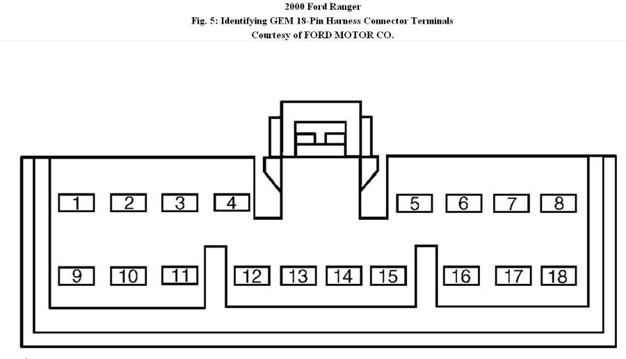
Using ohmmeter, measure resistance of Violet/Orange wire between terminal No. 2 on battery saver relay socket and terminal No. 8 on GEM 18-pin harness connector. See Fig. 5 and Fig. 15. If resistance is less than 5 ohms, replace GEM. Clear DTCs and retest system. If resistance is not less than 5 ohms, repair open in Violet/Orange wire. Clear DTCs and retest system.
(Figure 5)
36. Measure Circuit 779 (Brown Wire) Voltage
Turn ignition off. Disconnect transfer case 8-pin connector. Turn ignition on, engine off. Trigger GEM active command SHIFT CLUTCH to ON. Using DVOM, measure voltage between ground and terminal No. 8 on transfer case harness connector. See Fig. 6. If voltage is more than 10 volts, go to next step. If voltage is not more than 10 volts, go to step 38.
![]()
(Figure 6)
37. Check Circuit 779 (Brown Wire) For Voltage
Trigger GEM active command SHIFT CLUTCH to OFF. Using DVOM, check for voltage on Brown wire between ground and terminal No. 8 on transfer case harness connector. See Fig. 6. If voltage is not present, replace electric clutch relay. Clear DTCs and retest system. If voltage is present, go to next step.
38. Check Circuit 779 (Brown Wire) For Short To Voltage
Turn ignition off. Disconnect electric clutch relay. Turn ignition on, engine off. Using DVOM, check for voltage on Brown wire between ground and terminal No. 3 on electric clutch relay socket. See Fig. 15. If voltage is present, repair short to voltage in Brown wire. Clear DTCs and retest system. If voltage is not present, go to next step.
39. Check Electric Clutch Relay Switching Circuit
Using DVOM, measure voltage on Dark Green/Light Green wire between ground and terminal No. 5 on electric clutch relay socket. See Fig. 15. If voltage is more than 10 volts, go to next step. If voltage is not more than 10 volts, check power distribution box mini-fuse No. 3 (20-amp). Replace if necessary. If fuse is okay, repair Dark Green/Light Green wire. Clear DTCs and retest system.
40. Check Circuit 779 (Brown Wire) For Open
Using ohmmeter, measure resistance of Brown wire between terminal No. 3 on electric clutch relay socket and terminal No. 8 on transfer case 8-pin harness connector. See Fig. 6 and Fig. 15. If resistance is less than 5 ohms, replace clutch relay. Clear DTCs and retest system. If resistance is not more than 5 ohms, repair open in Brown wire. Clear DTCs and retest system.
41. Check Electric Shift Control Module
Trigger GEM active command CW/CCW to ON. Monitor GEM PIDs MTR_CCW and MTR_CW. If GEM PIDs display ON, go to next step. If GEM PIDs display ON-B-, go to step 47.
42. Check Electric Shift Control Module
Trigger GEM active command CW/CCW to OFF. Monitor GEM PIDs MTR_CCW and
MTR_CW. If GEM PIDs display OFF, go to step 50. If GEM PIDs display OFFO-G, go to next step.
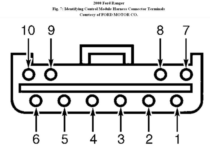
43. Measure Voltage To Electric Shift Control Module Coils (Light Green/Orange Wire)
Turn ignition off. Disconnect shift control module connector. See Fig. 2. Using DVOM, measure voltage on Light Green/Orange wire between ground and terminal No. 5 on shift control module harness connector. See Fig. 7. If voltage is more than 10 volts, go to next step. If voltage is not more than 10 volts, repair Light Green/Orange wire. Clear DTCs and retest system.
(Figure 7)
44. Check Circuit 513 (Brown/Pink Wire) For Open
Disconnect GEM 22-pin connector. See Fig. 2. Using ohmmeter, measure resistance of Brown/Pink wire between terminal No. 9 on shift control module harness connector and terminal No. 17 on GEM harness connector. See Fig. 3 and Fig. 7. If resistance is less than 5 ohms, go to next step. If resistance is not less than 5 ohms, repair open in Brown/Pink wire. Clear DTCs and retest system.
45. Check Circuit 339 (Gray Wire) For Open
Using ohmmeter, measure resistance of Gray wire between terminal No. 8 on shift control module harness connector and terminal No. 16 on GEM harness connector. See Fig. 3 and Fig. 7. If resistance is less than 5 ohms, go to next step. If resistance is not less than 5 ohms, repair open in Gray wire. Clear DTCs and retest system.
46. Check Circuits 513 (Brown/Pink Wire) & 339 (Gray Wire) For Short To Ground
Using ohmmeter, measure resistance between ground and terminals No. 8 (Gray wire) and No. 9 (Brown/Pink wire) on shift control module harness connector. See Fig. 7. If resistance for both circuits is more than 10 k/ohms, go to step 49. If resistance for either circuit is not more than 10 k/ohms, repair short to ground in Brown/Pink and/or Gray wire(s). Clear DTCs and retest system.
47. Check Circuit 339 (Gray Wire) For Short To Voltage
Turn ignition off. Disconnect shift control module connector and GEM 22-pin connector. See Fig. 2. Turn ignition on, engine off. Using DVOM, check for voltage on Gray wire between ground and terminal No. 8 on shift control module harness connector. See Fig. 7. If voltage is present, repair short to voltage in Gray wire. Clear DTCs and retest system. If voltage is not present, go to next step.
48. Check Circuit 513 (Brown/Pink Wire) For Short To Voltage
Using DVOM, check for voltage on Brown/Pink wire between ground and terminal No. 9 on shift control module harness connector. See Fig. 7. If voltage is present, repair short to voltage in Brown/Pink wire. Clear DTCs and retest system. If voltage is not present, go to next step.
49. Check Electronic Shift Control Module Coils
Using ohmmeter, measure resistance between terminal No. 5 and terminals No. 8 and 9 on shift control module harness connector. See Fig. 7. Resistance for both circuits should be 60-110 ohms. If resistance for either circuit is between 60-110 ohms, replace GEM. Clear DTCs and retest system. If resistance is not 60-110 ohms, replace shift control module. Clear DTCs and retest system.
50. Measure Voltage To Electric Shift Motor
Turn ignition off. Disconnect transfer case 8-pin connector. Turn ignition on, engine off. Trigger GEM active command CW/CCW to ON. Using DVOM, measure voltage between ground and terminals No. 4 (Yellow wire) and No. 7 (Orange wire) on transfer case 8-pin harness connector. See Fig. 7. If voltage for either circuit is more than 10 volts, go to step 52. If voltage for either circuit is not more than 10 volts, go to next step.
51. Measure Voltage To Electronic Shift Control Module Circuit 704 (Dark Green/Light Green Wire)
Turn ignition off. Disconnect electronic shift control module connector. See Fig. 2. Using DVOM, measure voltage on Dark Green/Light Green wire between ground and terminal No. 3 on shift control module harness connector. If voltage is more than 10 volts, go to step 55. If voltage is not more than 10 volts, check power distribution box fuse No. 3 (20-amp). If fuse is okay, repair open in Dark Green/Light Green wire. Clear DTCs and retest system.
52. Measure Voltage To Electric Shift Motor
Turn ignition on, engine off. Trigger GEM active command CW/CCW to OFF. Using DVOM, measure voltage between ground and terminals No. 4 (Yellow wire) and No. 7 (Orange wire) on transfer case 8-pin harness connector. See Fig. 6. If voltage for either circuit is more than 10 volts, go to next step. If voltage is not more than 10 volts for either circuit, go to step 54.
53. Check Circuits 777 (Yellow Wire) & 778 (Orange Wire) For Short To Voltage
Turn ignition off. Disconnect electronic shift control module connector. See Fig. 2. Turn ignition on, engine off. Using DVOM, measure voltage between ground and terminals No. 4 (Yellow wire) and No. 7 (Orange wire) on transfer case 8-pin harness connector. See Fig. 6. If voltage is present, repair short to voltage in Orange and/or Yellow wire(s). Clear DTCs and retest system. If voltage is not present, replace electronic shift control module. Clear DTCs and retest system.
54. Check Circuits 777 (Yellow Wire) & 778 (Orange Wire) For Open
Trigger GEM active command CW/CCW to OFF. Using ohmmeter, measure resistance between ground and terminals No. 4 (Yellow wire) and 7 (Orange wire) on transfer case 8-pin harness connector. See Fig. 6. If resistances are less than 5 ohms, reconnect transfer case 8-pin connector and go to step 58. If resistances are not less than 5 ohms, go to step 57.
55. Check Circuit 777 (Yellow Wire) For Open
Turn ignition off. Disconnect electronic shift control module connector. Using ohmmeter, measure resistance of Yellow wire between terminal No. 7 on electronic shift control module connector and terminal No. 4 on transfer case 8-pin harness connector. If resistance is less than 5 ohms, go to next step. If resistance is not less than 5 ohms, repair open in Yellow wire. Clear DTCs and retest system.
56. Check Circuit 778 (Orange Wire) For Open
Using ohmmeter, measure resistance of Orange wire between terminal No. 10 on electronic shift control module connector and terminal No. 7 on transfer case 8-pin harness connector. If resistance is less than 5 ohms, go to next step. If resistance is not less than 5 ohms, repair open in Orange wire. Clear DTCs and retest system.
57. Check Ground To Electronic Shift Control Module
Turn ignition off. Disconnect electronic shift control module connector. Using ohmmeter, measure resistance between ground and terminal No. 1 (Black wire) on shift control module connector. If resistance is less than 5 ohms, replace electronic shift control module. Clear DTCs and retest system. If resistance is not less than 5 ohms, repair Black wire. Clear DTCs and retest system.
58. Check Contact Plate Switches
Turn ignition on, engine off. Monitor GEM PIDs PLATE_A, PLATE_B, PLATE_C and PLATE_D. Place 4WD mode switch in 2WD position and record PID values. Depress brake pedal. Place transmission in Neutral. Move 4WD mode switch to 4X4 LOW position and record PID values. Compare PIDs recorded with the following table. See 4WD MODE SWITCH PID OUTPUT table. If PIDs match with table, inspect and repair transfer case for possible internal malfunction. Clear DTCs and retest system. If PIDs do not match table, go to next step.
59. Check Contact Plate Switch “D” Circuits 771 (Pink/Yellow Wire) and 762 (Yellow/White Wire)
Turn ignition off. Disconnect transfer case 8-pin connector. Turn ignition on. Monitor GEM PID PLATE_D. Scan tool should display OPEN. Connect jumper wire across terminals No. 5 and 6 on transfer case 8-pin harness connector. Verify PID indicates OPEN. If PLATE_D PID changes state, go to step 62. If PLATE_D PID does not change state, go to next step.
60. Check Circuit 771 (Violet/Yellow Wire) For Short To Voltage
Turn ignition off. Disconnect GEM 22-pin harness connector. See Fig. 2. Measure voltage on Violet/Yellow wire between ground and terminal No. 5 on transfer case 8-pin harness connector. See Fig. 6. If voltage is more than 10 volts, repair short to voltage in Violet/Yellow wire. If voltage is not present, go to next step.
61. Check Circuit 771 (Violet/Yellow Wire) For Short To Ground
Turn ignition off. Disconnect GEM 22-pin harness connector. See Fig. 2. Measure resistance of Violet/Yellow wire between ground and terminal No. 5 on transfer case 8-pin harness connector. See Fig. 6. If resistance is more than 10 k/ohms, go to next step. If resistance is not more than 10 k/ohms, repair short to ground in Violet/Yellow wire. Clear DTCs and retest system. If malfunction is still present, go to step 64.
61. Check Circuit 771 (Violet/Yellow Wire) For Open
Measure resistance of Violet/Yellow wire between terminal No. 21 on GEM 22-pin harness connector and terminal No. 5 on transfer case 8-pin harness connector. See Fig. 3 and Fig. 6. If resistance is less than 5 ohms, go to next step. If resistance is not less than 5 ohms, repair open in Violet/Yellow wire. Clear DTCs and retest system.
63. Check Circuit 762 (Yellow/White Wire) For Open
Measure resistance of Yellow/White wire between terminal No. 12 on GEM 22-pin connector and terminal No. 6 on transfer case 8-pin harness connector. See Fig. 3 and Fig. 6. If resistance is less than 5 ohms, go to next step. If resistance is not less than 5 ohms, repair open in Yellow/White wire. Clear DTCs and retest system.
64. Check Contact Plate Switch “C” Circuits 762 (Yellow/White Wire) & 770 (White Wire)
Monitor GEM PID PLATE_C. Scan tool should display OPEN. Connect jumper wire between terminals No. 1 and 6 on transfer case 8-pin harness connector. See Fig. 6. PID should display OPEN. If PLATE_C PID changes state, go to step 67. If PLATE_C PID does not change state, go to next step.
65. Check Circuit 770 (White Wire) For Short To Voltage
Turn ignition off. Disconnect transfer case electronic shift motor. Disconnect GEM 22-pin harness connector. See Fig. 2. Turn ignition on. Check for voltage on White wire between ground and terminal No. 1 on transfer case 8-pin harness connector. See Fig. 6. If voltage is present, repair short to voltage in White wire. Clear DTCs and retest system. If voltage is not present, go to next step.
66. Check Circuit 770 (White Wire) For Short To Ground
Turn ignition off. Measure resistance of White wire between ground and terminal No. 1 on transfer case 8-pin harness connector. See Fig. 6. If resistance is more than 10 k/ohms, go to next step. If resistance is not more than 10 k/ohms, repair short to ground in White wire. Clear DTCs and retest system. If malfunction is still present, reconnect transfer case 8-pin harness connector, and go to next step.
67. Check Circuit 770 (White Wire) For Open
Measure resistance of White wire between terminal No. 20 on GEM 22-pin harness connector and terminal No. 1 on transfer case 8-pin harness connector. See Fig. 3 and Fig. 6. If resistance is less than 5 ohms, go to next step. If resistance is not less than 5 ohms, repair open in White wire. Clear DTCs and retest system.
68. Check Contact Plate Switch “B” Circuits 762 (Yellow/White Wire) & 764 (Brown/White Wire)
Monitor GEM PID PLATE_B. Connect jumper wire across terminals No. 2(Brown/White wire) and No. 6 (Yellow/White wire) on transfer case 8-pin harness connector. If PLATE_B PID changes state, go to step 71. If PLATE_B PID does not change state, go to next step.
69. Check Circuit 764 (Brown/White Wire) For Short To Voltage
Turn ignition off. Disconnect transfer case electric shift motor. Disconnect GEM 22-pin harness connector. See Fig. 2. Check for voltage on Brown/White wire between ground and terminal No. 2 on transfer case 8-pin harness connector. See Fig. 6. If voltage is present, repair short to voltage in Brown/White wire. Clear DTCs and retest system. If voltage is not present, go to next step.
70. Check Circuit 764 (Brown/White Wire) For Short To Ground
Measure resistance of Brown/White wire between ground and terminal No. 2 on transfer case 8-pin harness connector. See Fig. 6. If resistance is more than 10 k/ohms, go to next step. If resistance is not more than 10 k/ohms, repair short to ground in Brown/White wire. Clear DTCs and retest system. If malfunction is still present, reconnect transfer case 8-pin harness connector and go to step 72.
71. Check Circuit 764 (Brown/White Wire) For Open
Measure resistance of Brown/White wire between terminal No. 19 on GEM 22-pin harness connector and terminal No. 2 on transfer case 8-pin harness connector. See Fig. 3 and Fig. 6. If resistance is less than 5 ohms, go to next step. If resistance is not less than 5 ohms, repair open in Brown/White wire. Clear DTCs and retest system.
72. Check Contact Plate Switch “A” Circuits 762 (Yellow/White Wire) & 763 (Orange/White Wire)
Monitor GEM PID PLATE_A. Scan tool should display OPEN. Connect jumper wire across terminals No. 3 (Orange/White wire) and No. 6 (Yellow/White wire) on transfer case 8-pin harness connector. If PLATE_A PID changes state, go to step 75. If PLATE_A PID does not change state, go to next step.
73. Check Circuit 763 (Orange/White Wire) For Short To Voltage
Disconnect transfer case electric shift motor. Disconnect GEM 22-pin harness connector. See Fig. 2. Turn ignition on. Check for voltage on Orange/White wire between transfer case electric shift motor terminal No. 3 and ground on transfer case 8-pin harness connector. See Fig. 6. If voltage is present, repair short to voltage in Orange/White wire. Clear DTCs and retest. If voltage is not present, go to next step.
74. Check Circuit 763 (Orange/White Wire) For Short To Ground
Turn ignition off. Measure resistance of Orange/White wire between ground and terminal No. 3 on transfer case 8-pin harness connector. See Fig. 6. If resistance is more than 10 k/ohms, go to next step. If resistance is not more than 10 k/ohms, repair short to ground in Orange/White wire. Clear DTCs and retest system.
75. Check Circuit 763 (Orange/White Wire) For Open
Measure resistance of Orange/White wire between terminal No. 18 on GEM connector and terminal No. 3 on transfer case 8-pin harness connector. See Fig. 3 and Fig. 6. If resistance is less than 5 ohms, replace shift motor. Clear DTCs and retest system. If resistance is not less than 5 ohms, repair open in Orange/White wire. Clear DTCs and retest system.
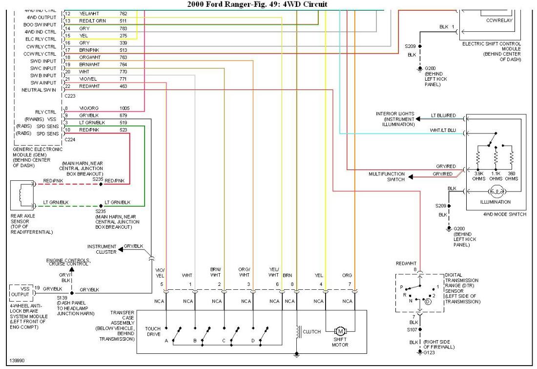
Wiring Diagrams