
Contributed By Denise Price ‘Yeehaw’
1) Read the instructions completely and carefully before you begin. ( refer to part’s list and the picture diagrams).
NOTE: if the vehicle is equipped with a manual transmission, part #3700 shift lever extension will be required to complete installation. If the vehicle is equipped with front tow hooks, they will be removed and cannot be reinstalled after the bumper has been lifted. If you wish to leave the tow hooks on the vehicle, the front bumper cannot be lifted. (not true. keep the bumper, lose the valance, keep the tow hooks)
2) Park the vehicle on a clean, dry flat (level) surface. Block the tires so the vehicle cannot roll in either direction.
3) Disconnect both battery cables. Be sure to disconnect the negative cable first, then the positive cable. Remove the airbag fuses from the fuse box in the interior and under the hood ( refer to the owner’s manual).
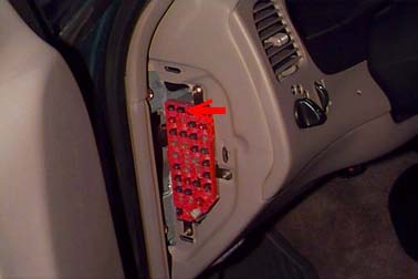
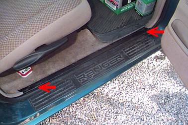
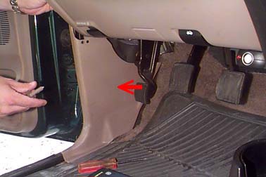
4) Remove the four (4) screws that mount each door jamb scuff plate to the body. Remove the side kick panels by gently pulling out on the kick panels. Be careful not to damage the plastic tabs that mount the kick panels to the body.
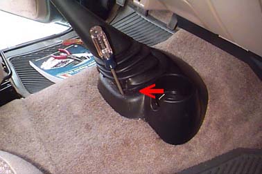
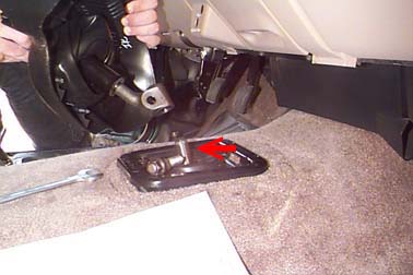
Manual Transmission Models Only. Remove the screws that mount the shift console to the floorboard. Pull the boot up to reveal the nut and wedge stud that attach the upper shift lever to the lower shift lever. Remove the nut from the right side of the wedge stud. Install the nut on the left side of the wedge stud. Tighten the nut to remove the stud. After the stud has been removed, slide the upper shift lever off of the lower shift lever. Install part # 3700 shift extension on the lower shift lever. Insert the 1/8″ x 1/2″ roll pin in the hole in line with the slot on the extension. Install the 5/16″ nut on the 5/16″ x 1″ bolt with the nylock toward the head of the bolt. Align the roll pin with the slot on the side of the lower shift lever. Insert the 5/16″ bolt and nut assembly into the threaded hole on the extension. The hole should be aligned with the flat milled area at the top of the lower shift lever. Tighten the 5/16″ bolt securely. After the bolt has been tightened, tighten the nut against the extension.
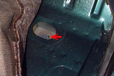
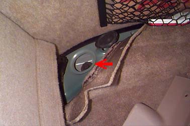
5) Pull the carpeting back to reveal the cab mounting bolt access covers. Remove the access covers to expose the cab mounting bolts. There should be one access hole on each side of the floorboard behind the rear seat. On extra cab models: fold up the rear seats, remove the side panel, and pull the carpeting back to expose the access holes.
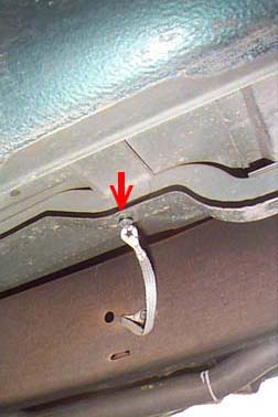
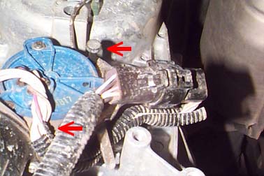
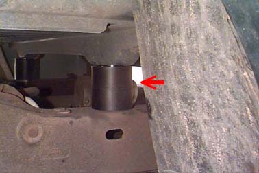
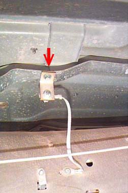
6) There are two (2) ground straps that are connected to the body and the middle cab mount on the frame. Remove the straps from the frame. They will be reconnected after the lifting operation is complete.
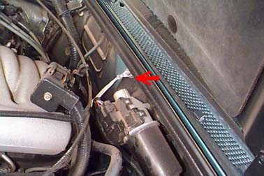
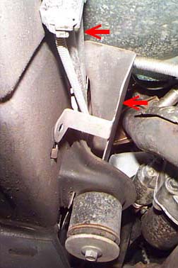
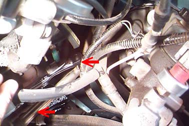
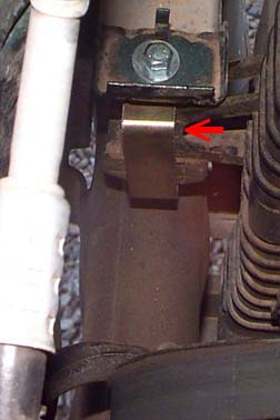
7) There is a ground strap that runs from the back of the engine to a stud on the firewall. Remove the nut that mounts the ground strap to the stud on the firewall. Install the studded ground strap extension bracket to the stud on the firewall. The stud on the bracket should be pointing toward the front of the vehicle. Install the stock nut on the stud and tightened the nut securely. Install the ground strap to the stud protruding from the bracket. Install a 1/4″ washer and nylock nut on the stud. Tighten securely. We recommend the use of Loctite or similar adhesive on all mounting hardware.
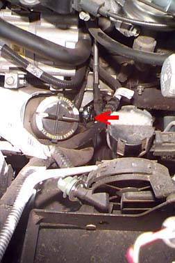
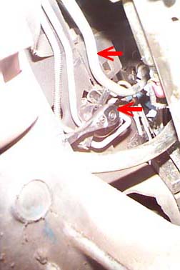
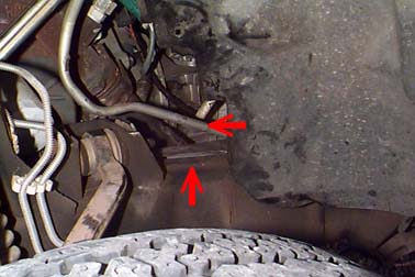
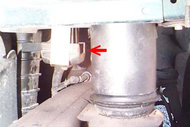
8) There is a wire loom that runs to the battery and driver’s side fenderwell. This wire loom is attached to the driver’s side of the engine with a bracket. There is a nut that attaches the bracket to a stud protruding from the engine. Remove the nut from the stud. Remove the bracket from the stud. Remove the wire loom from the bracket. The bracket will be repositioned after the body has been lifted.
9) Automatic Transmission Model Only. Automatic transmissions are equipped with cable operated shift and should require no modifications. Remove the cable from any clips that are holding the cable to the body that may cause binding while lifting.
10) 4 Wheel Drive Models Only. If the vehicle is equipped with electronic 4 wheel drive shift control, remove the wire loom mounting tab from the bracket on the rear of the transfer case under the driver’s seat. The wire loom will be remounted after the lifting operation is complete.
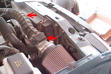
11) Loosen the clamp that mounts the air intake hose to the intake manifold. Disconnect any wires or other hoses connected to the main intake hose. Remove the hose from the air cleaner housing by releasing the large clamp that holds the assembly together. Remove the hose from the vehicle.
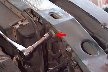
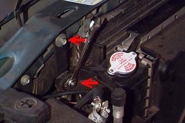
12) Remove the two (2) bolts that mount the top of the radiator to the core support. Carefully lift the radiator up and off of the lower mounting pads. Reposition the radiator under the lower mounting pads. The radiator will be mounted to new brackets under the stock pads. Remove the rubber from the lower mounts.
13) Remove the brake lines from the plastic clips on the driver’s side fenderwell and frame rail. The brake lines will need to carefully bent to gain slack. Gently bend the lines so they can flex while lifting. Be extremely gentle with the lines, they could easily be damaged if they are not bent properly.
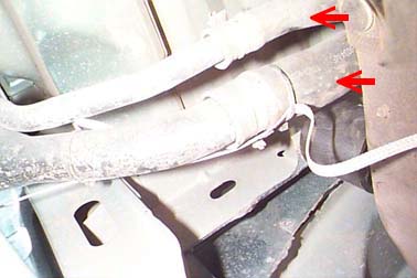
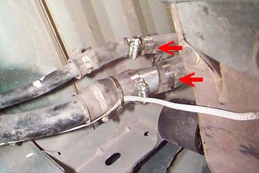
14) There is a sheet metal cover on the inside of the driver’s side frame rail that covers the lines running to the fender well area (if equipped). Remove the screws that mount the cover to the frame. Remove the cover from the vehicle. The larger diameter line (the top line) needs to be removed from the forward mount bracket, and bent to gain slack. Remove the bolt that closes the mounting bracket over the lines. Remove the top portion of the bracket. Reinstall the top portion of the bracket and install the mounting bolt securely. Carefully and gently bend the line upward. Check the line again while lifting the truck. Bend the line as necessary to gain the proper amount of slack. Be especially careful not to damage the line or anything attached to the line.
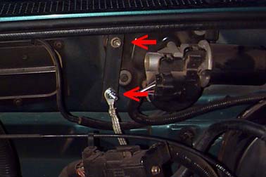
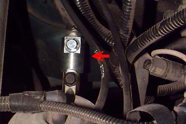
15) Important: While working with the vehicle steering do not allow the steering wheel to turn independently from the steering gear. If the steering is not reassembled in the exact position that it currently is in, the air bag system could malfunction. If this occurs, the repair will be quite costly. Mark the upper and lower sections of the steering shaft where they are connected at the firewall. This will insure proper connection after the steering extension has been installed. Remove the bolt that connects the upper steering shaft in the engine compartment. Slide the lower steering shaft down and off of the upper shaft. Install the female end of the steering extension over the upper steering shaft. Install a 3/8″ washer and nylock nut on the bolt. Tighten securely. We recommend the use of a Loctite or similar adhesive on all steering hardware. Connect the lower steering shaft to the steering extension. Realign the marks on the upper and lower steering shaft. Insert the male end of the steering extension into the lower steering shaft. Insert the stock bolt through the lower steering shaft, the steering extension, and threading into the stock nut. Tighten securely. We recommend the use of a Loctite or similar adhesive on all steering hardware.
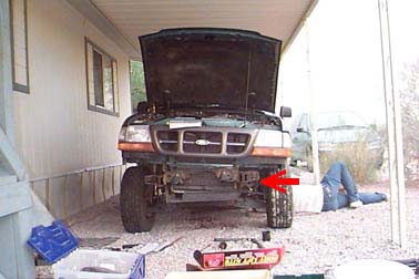
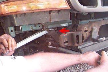
16) Remove the front bumper from the vehicle. If the vehicle is equipped with fog lights under the front bumper, disconnect the wiring from the connector going to the fog lights. If the vehicle is equipped with tow hooks, remove the three bolts mount each tow hook to the frame cross member behind the bumper. The tow hooks will not be reused. Remove the four (4) nuts ( two on each side) that mount the front bumper to the frame. Remove the front bumper from the vehicle.
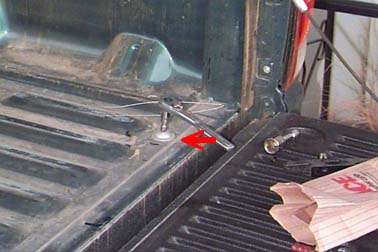
17) Measure the distance between the cab and the bed. Record these measurements for proper alignment after the lifting operation is complete. Loosen, but do not remove all six (6) cab mounting bolts. They are located as follows ( one on each side); at the front of the vehicle on each side of the radiator, in the front floorboard, and behind the front seat at the rear of the cab.
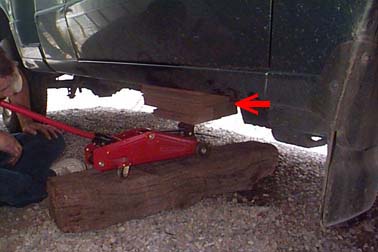
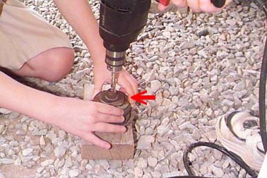
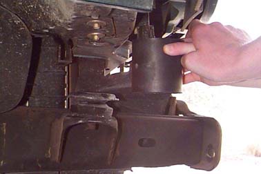
18) Remove the cab bolts from the passenger side of the vehicle only. Be sure that the doors are closed. This will help prevent the cab from flexing during the lifting operation. Using a hydraulic jack and a wooden block, slowly lift the passenger side of the cab just high enough to place the spacer blocks on the mounting pads. Be sure to continually check for any hoses, wires, cables, etc. that may be binding. Double check the brake lines and the tube on the driver’s side to be sure that there is enough slack to continue lifting. Remove the front mounting pad from the vehicle. Using a 1/2″ drill, drill the threads out of the bushing sleeve. This will allow the new bolt to slide all the way through the sleeve. Replace the bushing on the vehicle. Place the spacer blocks on top of the stock rubber mounting bushings. For the front cab mount at the core support, insert a 12mm x 180mm bolt with the 7/16″ uss washer from the bottom through the stock bottom washer and rubber cone under frame mount, through the stock bushing on top of the frame mount, through the spacer block, through the core support and through the stock top washer. Install the stock nut on the bolt. Do Not tighten. For the mount at the front floorboard, insert a 12mm x 140mm bolt with a 7/16″ uss washer from the top through the body, through the spacer block, through the stock bushing on top of the frame mount through the bottom bushing cone and stock washer under the frame mount. Install the stock nut on the bolt. Do Not tighten. For the mount at the rear of the cab, insert a 12mm x 160 mm bolt with a 7/16″ uss washer from the top through the stock top washer, through the body , through the spacer block, through the bushing on top of the frame mount, through the bushing cone and stock washer under the frame mount. Install the stock nut on the bolt. Do Not tighten. Be sure that all stock washers, bushings, and other mounting hardware (except the stock bolts) are in the original locations. Do Not tighten. Lower the body onto the spacer blocks. Remove the jack from the passenger side of the cab.
19) Repeat step 18 for the driver’s side of the cab. Realign the cab and bed (refer to the measurements made earlier). Tighten all cab mounting bolts securely. We recommend the use of Loctite or similar adhesive on all mounting hardware.
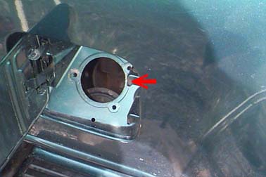
20) Remove the screws that mount the fuel filler neck to the body. The filler hose will need to be lengthened.
21) Remove the rear bumper. If the vehicle is equipped with a rear tow hook, remove the three (3) nuts that mount the tow hook to the frame. Remove the tow hook from the vehicle. Disconnect the license plate lights from the rear bumper. Remove the two (2) bolts that mount the rear bumper brackets to the frame. Remove the rear bumper from the vehicle.
22) Loosen, but Do Not remove all eight (8) {six on short bed models} bed mounting bolts. A t-55 torx socket is required to loosen the bed mounting bolts. Remove the bed mounting bolts on the passenger side of the bed only. Using a hydraulic jack and a wooden block, slowly lift the passenger side of the bed just high enough to place the spacer blocks on the frame. Be sure to continually check for any wires, hoses, cables, etc. that may be binding. Insert the new mounting bolts with a 7/16″ washer from the top through the body, the spacer block, and threading into the stock nut that is attached to the frame. A 12mm x 200 mm bolt is used in the front bed mount, and 12mm x 180mm bolts are used in the other locations. Do Not tighten.
23) Repeat step 22 for the driver’s side of the vehicle. Realign the bed to the cab. Tighten all bed mounting bolts securely. We recommend the use of Loctite or similar adhesive on all mounting hardware.
24) Replace the access hold covers over the access holes. Replace the carpeting to its original position. Replace the side kick panels on the front and in the rear (extra cab only). Do Not replace the shift boot assembly at this time. Replace the doorjamb kick plates. Tighten all mounting screws securely.
25) Manual Transmissions Only. Install the upper part of the shift lever onto the extension. Install the nut on the end of the wedge stud. Tighten until the lever is securely in place. Reinstall the boot assembly. Tighten both mounting screws securely.
26) 4 Wheel Drive Models Only. On vehicles equipped with electronic 4 wheel drive shift control (shift on the fly) wrap the wire loom bracket (supplied in the kit) around the wires at the transfer case. Using a 1/4″ x 1″ bolt, two 1/4″ washers, and 1/4″ nylock nut mount the new wire loom bracket to the stock bracket at the rear of the transfer case. Be sure that there is ample slack in the wires. Tighten the mounting hardware securely. On vehicles equipped with manual 4 wheel drive, check the 4 wheel drive shift lever operation. Check to see if the shift lever will engage in all 4 wheel drive ranges. Reinstall the shift boot assembly. Check the shift lever operation again. It may be necessary to modify the boot assembly to allow for proper shift lever operation. Mount the shift boot to the floorboard. Reinstall the shift knob. Check both shift levers’ operation once more. Be sure that there is ample engagement in all gears and 4 wheel drive ranges.
27) Automatic Transmissions Only. Reattach the shift cable to the mounting clips on the firewall/bell housing area. It may not be possible to reattach the cable to all of the mounting tabs, but attach it to as many as possible.
28) A/C Models Only. If the vehicle is equipped with air conditioning, the a/c hose is rubbing on the bottom of the alternator and needs to be insulated. There is a 6″ long piece of 3/4″ hose included in the kit. Split the hose lengthwise. Place the 3/4″ hose over the a/c hose between the a/c hose and the alternator. Secure the hose in place using two cable ties provided in the kit.

29) Reinstall the wire loom mounting bracket to the driver’s side of the engine. Tighten the mounting hardware securely. Reattach the wire loom to the mounting bracket. Be sure that there is ample slack in the wiring to reach the battery and the driver’s side fender well.
30) Reinstall the sheet metal cover on the inside of the driver’s side frame rail. The large tube should be routed between the top of the cover. Be sure that there is ample slack in the line and that it is not rubbing on anything that could wear a hole in the line or hinder the operation of any component. Tighten the cover’s mounting screws securely.
31) Check the brake lines that were removed from the clips on the driver’s side fender well. Be sure that the lines have extended and are not binding. If the lines are binding. carefully and gently bend them to gain more slack.
32) Remount the radiator. Mount the rubber cushion that the radiator sat on in the radiator drop down tubes. The nipple on the bottom of the cushion should fit in the small hole in the tube. The top of the tube will mount to the bottom of the stock mount. Slide the tube with the cushion around the arm on the radiator so the arm will sit on the cushion. Mount the tube with the radiator to the bottom of the stock radiator mount by installing a 5/16″ x1″ bolt and 5/16″ large washer from the top of the stick mount and screwing down into the nut that is attached to the top of the tube. Do Not tighten. Mount the radiator drop down brackets to the core support where the radiator was originally mounted. Mount the radiator mount to the stud on the radiator bracket. Install a 1/4″ washer and nylock nut on each stud. Do Not tighten. Adjust the fan to fan shroud clearance. It should be the same all the way around the radiator. Tighten all radiator mounting hardware. We recommend the use of Loctite or similar adhesive on all mounting hardware.
33) Reconnect the air intake hose to the air cleaner assembly and the intake manifold. Reconnect any wires or hoses that were disconnected from the intake hose.
34) Lengthen the fuel filler hose.
CAUTION: Always use extreme care when working around gasoline or any other flammable substance. Gasoline is highly explosive and can ignite with the slightest spark. Take precautions to prevent any leakage of fuel while the filler neck is disconnected. Fuel vapors can be harmful, be sure that the work area is well ventilated and free from sources of ignition (cigarettes, fire, sparks, etc.) Cut the fuel filler hose approximately half way between the fuel tank and the filler neck. Remove the clamp that attaches the vent hose to the filler neck. Slide one #28 hose clamp over each piece of the filler hose (top and bottom). Install the fuel filler extension between the two pieces of the filler hose. Make sure that the filler neck will reconnect to the body. Adjust the hose as necessary. Tighten the hose clamps securely over the filler extension. Cut the vent hose into two pieces in the middle of the hose. Reconnect the upper part of the hose to the nipple on the filler neck. Slide one #10 hose clamp over each piece of hose. Insert the vent hose extension between the two pieces of the vent hose. Adjust the vent hose. Tighten the hose clamp securely. NOTE: some models are quipped with a larger diameter vent hose. This hose can be adjusted and reconnected without using the extension. Reconnect the filler neck to the body. Install the stock mounting screws. Tighten the screws securely. Reinstall the filler cap.
35) Using the stock hardware, mount the “L” shaped ground strap brackets to each side of the frame rail where the body to frame ground straps were originally mounted. Mount the ground strap to the bracket using a 1/4″ x 1″ bolt, two 1/4″ washers and a 14″ nylock nut. Tighten the mounting hardware securely. Be sure to complete this procedure for both sides of the vehicle.
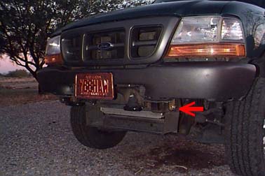
36) Reinstall the front bumper. If you wish to reinstall the two hooks, the bumper will be reinstalled in the stock position.
NOTE: if the vehicle is equipped with fog lights, refer to the template for timing the frame mount for clearance. Lay the template on the outside bumper frame mount. Align the hole and outside edge of the template with the hole and the outside edge of the frame mount. Mark the frame mount at the dotted line on the template. Cut the outside bracket according to the template. This will allow clearance for the fog lights. The bottom of the stock bumper bracket will need to be trimmed to clear the bottom of the frame horn. Refer to the diagram for trimming. Remove the stock bumper brackets from the bumper. Trim the bracket according to the diagram. Remount the stock bumper brackets to the bumper. Tighten all sock mounting hardware securely. Mount the bumper raising brackets to the bumper using the stock nuts. The studs on the new brackets should be pointing away from the bumper. Do Not tighten. Install the bumper on the vehicle with the studs going through the original mounting holes. Install a 1/2″ USS washer and 1/2″ nylock nut on each stud. Do Not tighten completely. Adjust the bumper from the side and up and down. Tighten all front bumper mounting hardware securely. We recommend the use of Loctite or similar adhesive on all mounting hardware.
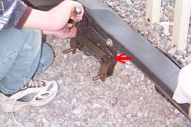
37) WARNING: THE REAR BUMPER BRACKETS PROVIDED IN THIS KIT ARE INTEDED TO ENHANCE THE APPEARANCE OF THE VEHICLE ONLY. THEY ARE NOT RATED FOR TOWING. ANY ATTEMPT TO TOW WITH THE REAR BUMPER AFTER THESE BRACKETS HAVE BEEN INSTALLED COULD RESULT IN DAMAGE TO THE VEHICLE AND SERIOUS PERSONAL INJURY. Remove the stock rear bumper brackets from the bumper (the outside supports will remain on the bumper). Using the stock hardware, mount the new rear bumper brackets to the bumper (the notch in the bumper bracket goes down). DO Not tighten. Mount the outside support brackets to the center hole (between the bends ) of the new brackets.
Note: some models have the outside supports welded to the center area of the bumper. It will not be possible to mount the outside supports to the new brackets on these models. Hold the bumper assembly in the position that it needs to be mounted. Using the brackets as a template, mark the frame through the holes in the new bumper brackets. Remove the bumper from the vehicle. Drill a 1/2″ hole in each location (there should be two {2} holes in each frame rail). Note: on vehicles equipped with the rear tow hook, an additional hole will need to be drilled in the new bumper bracket corresponding to the bolts for the tow hook. Drill a 1/2″ hole at this location. Using the four (4) 7/16″ x 1/2″ bolts, eight (8) 7/16″ washers, and four (4) 7/16″ nylock nuts provided; mount the bumper assembly to the frame. On vehicles equipped with tow hooks, use the stock hardware on the right side and 7/16″ hardware (described above) on the left. Adjust the bumper to body clearance. Be sure the tailgate will open properly. Tighten all rear bumper mounting hardware securely. Reconnect the license plate lights. We recommend the use of Loctite or similar adhesive on all mounting hardware. Note: after the rear bumper has been lifted, the spare tire crank will need to be accessed from behind the rear license plate. Carrying a screwdriver to remove the license plate is recommended.
38) Weld the overload support brackets to the frame. There are four (4) locations (two{2} on short bed models) where the cross supports rest just off of the frame and there are no mounting bolts ( over the wheel wells). Weld the overload support brackets to the frame in these locations. This is so the cross supports have something to rest on when a load is placed in the bed. We recommend that all welding be done by a certified welder only.
39) Reconnect both battery cables. Be sure to connect the positive cable first, then the negative cable. Replace the airbag fuse in the fuse box.
40) Place the warning label on the vehicle dash in plain sight of all vehicle occupants.
41) Double check the vehicle. Check once more for any wires, hoses, cables, etc. that may have missed earlier. Be sure that none are binding. Check the fan to fan shroud clearance. Make sure that the fan cannot make contact with the shroud. Start the engine. Listen for any unusual noises. Check the steering operation. Check the transmission and transfer case operation. Be sure that the transmission and transfer case engage properly in all gears and four (4) wheel drive ranges. Check all mounting hardware in 500 miles and as part of your regular maintenance schedule.
Thanks go to Brenda “Twink” for typing the PA instructions and Bill for helping break loose Ford’s “We Seal Everything with Loctite” fasteners….. -Dennis “Yeehaw”