
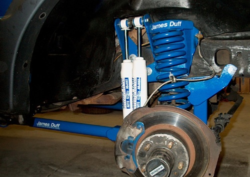
The Ranger front suspension is a mix of radius arms, which hold the axle in place, coil springs, I-beam flexing front axle and a sway bar. The pivot points on the frame for the I-beam suspension acts as a track bar. The length of the radius arms and the flex of the I-beam axle limit flex in these trucks. Tire size is also limited by the radius arms as you need to add lots of off-set to the rims to clear the radius arms when turning with big tires. Duff has created a new extended radius arm that not only allows the axle more travel, but they are angled inward, creating more turning radius without lots of wheel offset.
It is a good idea to spray everything with WD 40 before you start to undo stuff. Start a week or so beforehand and spray everything down – you will be glad that you did!
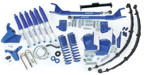
This is the new 5-inch Ranger lift for mid ‘90s Rangers. Duff sells their kits in stages 1-3. This is the stage three kit with full rear leaf springs and the front extended radius arms. The nice thing about the Duff kits is you can start with stage one and add components as you have the cash or need to increase the ability of your Ford 4×4.
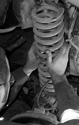
First up is lifting the vehicle and placing the frame on jack stands. Using a jack, the axle can then be lowered so the coils can be removed. After unbolting and removing the stock shocks, unbolt the retainer clip that holds the bottom of the coil in place. The coil can then be twisted out of the upper coil bucket.
With the axle firmly on jack stands, the radius arms can now be removed. Place a jack under the transmission and remove the stock transmission cross member. Unbolt the radius arm from the axle and grind or chisel the studs holding the frame bracket for the radius arm end. Remove the stock radius arm and bracket.
Using the existing transmission mount holes, bolt the new radius arm bracket in place. The bracket should be 5 inches back from the firewall body mount bracket. It may be necessary to enlarge the holes to 1/2 inch so the bolts will slide through. In some cases the third hole needed to bolt the bracket in place may be missing – use the bracket as a template and drill an extra 1/2 inch hole.
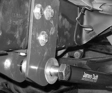
Thread a jam nut onto a rod end then thread the rod end all the way into the new radius arm, and back it off three turns. This will be your preliminary radius arm length. The rod end goes into the bracket with a 1-inch spacer on each side. Slide the one-inch bolt through the bracket, spacers and rod end and leave loose until both sides are ready and the new transmission cross member is installed. Attach the radius arm to the axle and torque the radius arm to axle bolts to 190-220 ft-lbs.
![]()
With both radius arms and brackets in place, the new transmission cross member can be slid up between the mounting brackets and aligned with the transmission mount. Slide the 1-inch bolt that goes through the rod end through the new cross member. Use the supplied grade-8 bolts to secure the rest of the cross member to the radius arm brackets. Torque all the bolts to the supplied specs including the bolts through the rod ends.
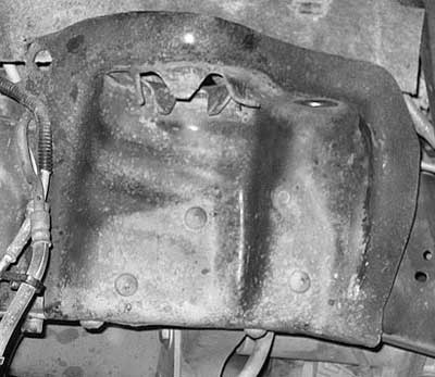
Next is the removal of the stock shock/coil bucket. We will be replacing these with the Duff dual front shock bucket. Use a grinder to remove the heads from the studs holding the bracket to the frame and remove the coil bucket. It will be necessary to unbolt the I-beam bracket on the passenger side in order to remove the coil bucket.
The new coil bucket uses the stock holes from the old coil bucket to bolt in place. Using the new coil bucket as a guide, drill out the old rivet holes to 1/2 inch and loosely place a bolt in each hole as you drill it. This will help you align the other holes as you drill them out. Torque all the bolts to 90 ft-lbs.
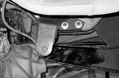
Two new holes will need to be drilled for the dual shock bracket. Install a 6 1/2 inch bolt through the hole in the coil bucket through the hole in the rear shock bracket. Measure 5 inches back from the bracket on the coil bucket and flush it with the bottom of the frame – clamp the bracket in place and drill the holes through the frame and attach with the supplied hardware.
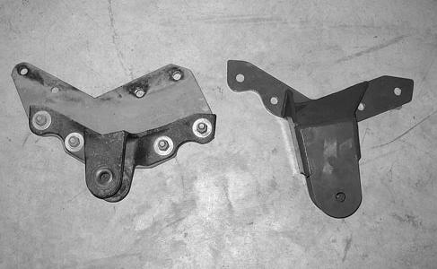
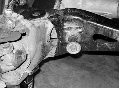
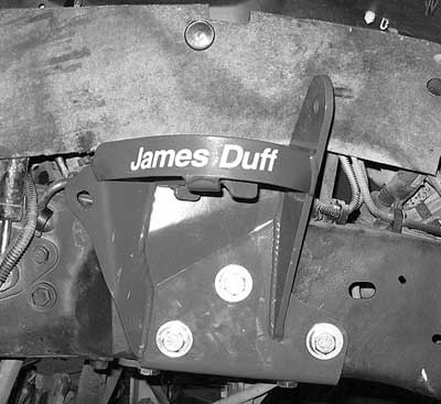
Above is the old factory axle beam mount bolted to a drop bracket from a previous lift. To the right of that is the new James Duff axle beam bracket.
Not done with the grinding yet! The old I-beam drop bracket will need to be removed from the engine cross member. The drop brackets are needed to keep the front axle aligned – remember the axle acts as the track bar keeping the truck going straight down the road.

On the passenger side the I-beam will need to be removed from the old bracket (like the cross member bracket) but the old bracket is bolted in place rather than riveted. Bolt the new bracket in place and bolt the I-beam into the new bracket.
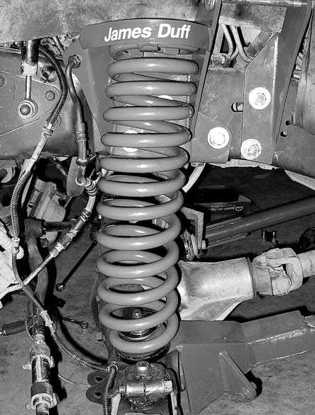
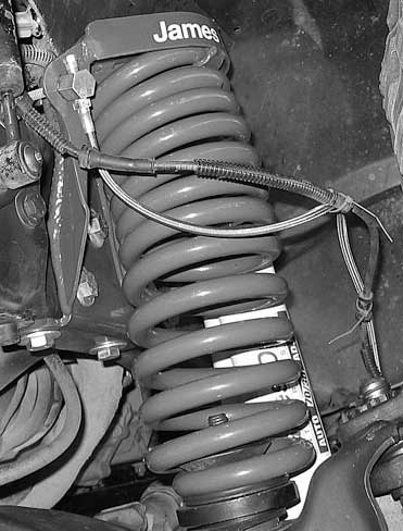
The stock bump stop can now be reinstalled and the new dual rate coil can be installed.
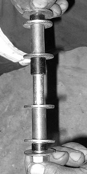
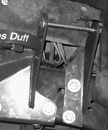
The long bolt in the upper bracket slides though the top of the dual shocks with sleeves and spacers like shown above. All the truck needs up front now are extended brake lines and a wheel alignment!
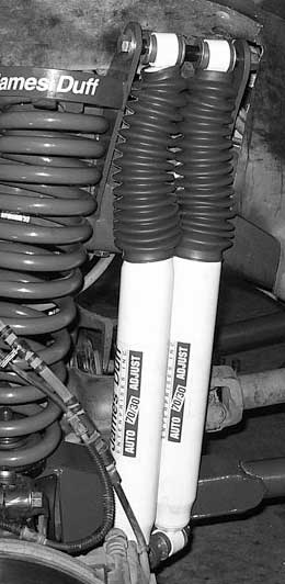

The kit came with extended stainless braided DOT brake lines. There is a bracket on the upper coil bucket to attach the supplied fitting and the lines directly replace the stock lines.

The rear is quite easy. Support the frame with jack stands – cut or unbolt the old U-bolts with a jack under the axle, lower the rear axle with a jack, unbolt and remove the old leaf spring and replace wit the new leaf spring. Raise the axle back up with the small blocks provided with the kit and torque the new U-bolts in place. Don’t forget to cut off the excess ends of the U-bolts.
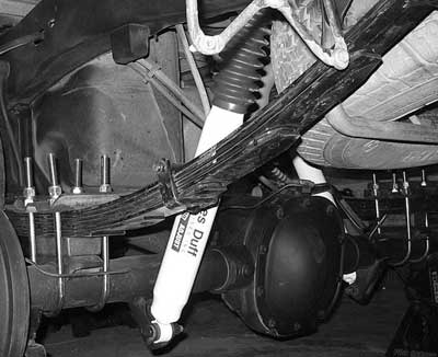
All there is left after all the bolts are tight is to install a set of 70/30 James Duff shocks out back!
Link: