
Article By:
- Jim Oaks
- 4x4Junkie
Introduction:
The term ‘Cut and Turn’ has been around well before it was ever used on the Ford Ranger, Bronco II or Explorer. Owners of these vehicles may think the term refers to “cutting” the TTB beams and “turning” the knuckle (or pivot) to gain lift without using drop brackets for the axle, however the term actually originated from a method used to correct the caster angle on a solid axle suspension where the differential pinion has been rotated up to correct the driveshaft angle after a lift. It involved rotating the inner knuckle (inner yoke or steering yoke) by cutting the weld out, turning the knuckle on the axle tube to correct the caster, and then re-welding it.
(Cut and turn on a solid front axle)
Alignment:
To better understand why a ‘Cut and Turn’ is done, you have to understand what ‘caster’ and ‘camber’ is.
|
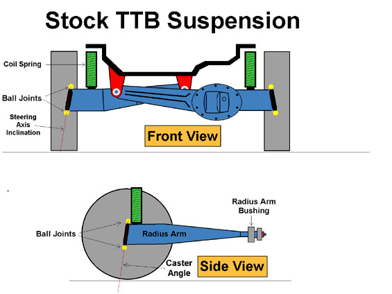
Caster:
Caster Angle is the amount of tilt through the centerline of the ball joints (or king pin) in your front axle. As seen above it is measured looking at the side of the vehicle with a (+) positive value being a tilt to the rear and a (-) negative value being a tilt to the front. Caster angle is what provides the return-to-center function of your steering. In most situations on a lifted/modified vehicle a caster angle of +4 to +6 degrees is ideal. Factory specs on Dana 44’s have been anywhere from 0 to +7.5 degrees.
You reset the caster at the knuckles when you do the cut and turn on a solid axle.
Camber:
Camber is the inward or outward tilt of the front tires as viewed from the front. Inward tilt is (-) negative, outward tilt is (+) positive. Proper camber distributes the load evenly across the tire’s tread. Improper camber makes the tire wear on one edge, and can cause the vehicle to pull to the side.
With a solid axle like a Dana 44 the camber angle is fairly fixed. On a TTB axle, the camber can be greatly affected when lifting the suspension. When doing a cut and turn on a Dana 35 TTB, camber is what you’re generally trying to effect.
Cut And Turn For A TTB Front Suspension:
A Note From Staff Member 4x4Junkie:
A Cut & Turn is primarily a modification for ‘go-fast’ (desert/prerunner) rigs, it greatly improves clearance under the axle for when you’re jumping/landing/blasting over whoops and thru dips.
In my travels on the forum, I’ve seen a number of trail and rock crawler guys who also get hooked on the idea of a C&T without understanding the liability it’s increased jacking effects have on the suspension (from the higher-mounted pivot points) and what it does to the truck’s handling when it unloads on a steep hill or other off-camber slow-speed situation. Trail crawlers are almost always better off with a good drop bracket suspension (leaving the beam geometry stock).
The Effect It Has On Your Suspension:
This brings us to the Dana 35 TTB suspension used on the front of the older Ford Ranger and Explorers.
Camber and Caster on a TTB are normally adjusted using an offset bushing around the upper ball joint stud (a single bushing adjusts both). However they have a fairly limited range of adjustment, which limits the amount you can lift the suspension to approximately 2 inches over the original factory height.
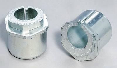
(Dana 35 caster/camber alignment bushings)
If you put a wrench on the bushing and turn it, you’ll be able to see your steering knuckle tilt forward and back, as well as tilt in and out to the side as the bushing rotates.
Using the (2) diagrams below, you can see how lifting a Dana 35 TTB greatly affects your caster and camber. It is the camber that will be most visually evident.
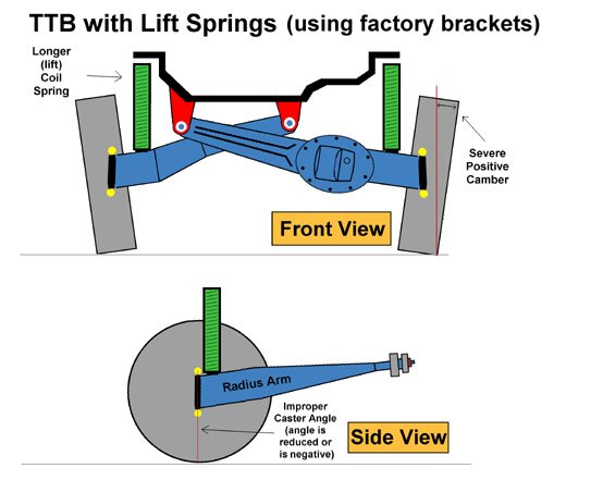
This amount of change in caster and camber is well beyond what is correctable using the alignment bushings shown above, so aftermarket TTB suspension kits normally include drop-down brackets for the axle beams and the radius arms. The brackets for the axle beams help to restore the camber, and brackets for the radius arms help with the caster. The alignment bushings are then used to fine-tune the final alignment.
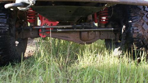
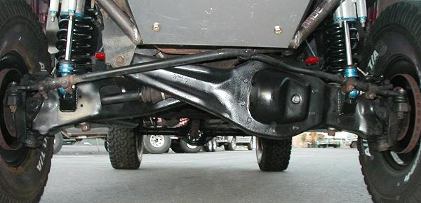
(Note the red Skyjacker drop bracket and how the beam maintains a horizontal line)
How ‘Cut And Turn’ Fits In To The Dana 35 TTB Suspension
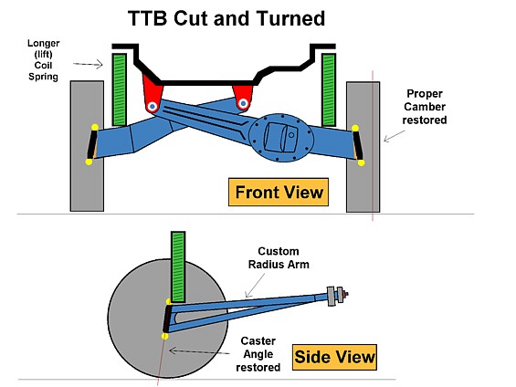
Ok, we’ve seen how lifting a Dana 35 TTB affects suspension angles. So how does a ‘cut and turn’ work on this style of setup?
In this situation, instead of using a drop-down bracket, the axle beam itself is modified to correct the camber, and (typically) a custom radius arm is used to correct the caster angle, removing the need for a radius arm drop bracket.
What Is Wrong With Using Drop Brackets:
One reason Cut and Turns were done in the past was because early drop bracket designs tended to be weak; their longer length created additional leverage on the bracket and vehicle frame which led to problems with bending and cracking with rough use. While better suspension kits such as Skyjacker and James Duff have successfully tackled these issues using larger and wider brackets that spread the load over a larger footprint, another reason to still do a Cut and Turn is the improved clearance under the axle & differential it offers; the brackets and beams don’t protrude down as far when the suspension fully compresses during jumps or while blasting through dips at high speed, possibly striking a rock or other object imbedded in the road and damaging them.
Methods of Cutting and Turning A Dana 35:
There have been various methods that people have used to cut and turn a Dana 35. They include:
Cutting and Relocating The Lower Ball Joint:
The most popular method by far is relocating the lower balljoint outward on the beam, and is the method currently in use at most desert racing shops. When using the stock axle pivot brackets and adding taller coils, the beams angle downward and the tire moves with it at the same angle (see diagrams above). To align the wheel properly, they relocate the lower ball joint outward to correct camber and make the wheel sit straight up and down.
How much you move the ball joint outward depends on how much lift you have. Remember that the beams are different lengths, so the distance you move the lower ball joint is likely to be different on each side.
There is no set degree or measurement to follow. One suggested method found for measuring was to mount the beams with the new coils, and measure the coil height. then pull everything apart, cut the lower ball joint seat out, and mount the beams. Block the beam so the distance between the beam and the upper coil bucket is the height you just measured with the coil. With 0-degree alignment bushings, move the ball joint seat out until you’re at 90 degrees to the floor. This will give you your new lower ball joint seat location. Now you just need to weld it up. Starting with the 0-degree bushing will give you room to fine tune the alignment after it’s all together.
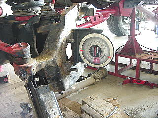
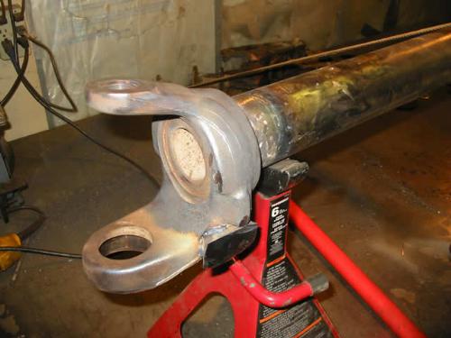
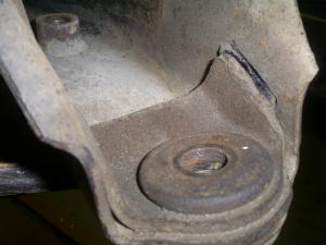
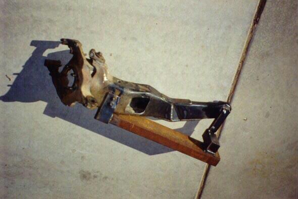
(Not the best photo, but gives you an idea of checking that the knuckle is 90-degrees. Knuckle should be turned straight forward)
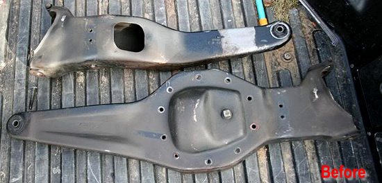
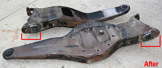
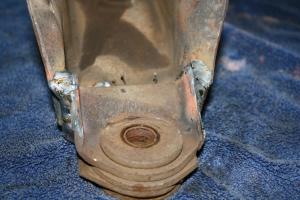
In these photos you can see where the lower ball joint has been pushed out, re-welded, and reinforced with a metal plate.
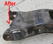
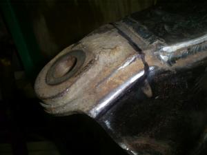
(Dana 44 TTB lower ball joint, but same idea)
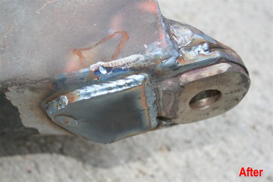
Here’s the lower ball joint seat moved outward, welded, and reinforced.
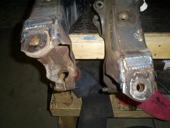
(Note – you’re looking at the bottom side of the driver and passenger beams)
Using this method will not cause any significant reduction in your axle/track width.
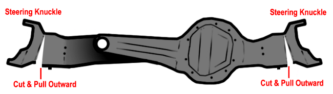
Cutting Before The Steering Knuckle:
Some people have done a cut and turn on the beam just before the knuckle. It shares the same idea as the ball joint method above by pushing the lower ball joint out, though it is not as straightforward as it looks (see note at the end of this section about misalignment of the axle shaft).
The description will sound similar to what is above:
When using the stock axle beam pivot brackets and adding taller coils, the beam angles downward and the tire moves with it at the same angle (see diagrams that are up above). To align the wheel properly, the axle beam is cut from the bottom just before the steering knuckle. This allows the knuckle to be tilted outward to correct camber and make the wheel straight up and down.
How much you move the knuckle outward depends on how much lift you have. Remember that the beams are different lengths, so the amount you move the knuckle will likely be different on each side.
There is no set degree or measurement to follow. You should be able to use the same method as described above. Mount the beams with the new coils and measure the coil height. Then pull everything apart, cut the beam from the bottom upwards just before the knuckle, and re-mount the beams. Block the beam so the distance between the beam and the upper coil bucket is the height you just measured with the coil. With 0-degree alignment bushings, tilt the knuckle out until your at 90-degrees to the floor. This will give you your new knuckle location. Starting with the 0-degree bushing will give you room to fine tune the alignment after it’s all together. Tack a small gusset to the bottom of the beam to hold the knuckle in place and then remove the beam for welding.
Important: You want to be careful filling the gap created when you cut and moved the knuckle. Excessive welding can create a great deal of heat and cause the metal to distort (bend). If you’re a good welder you’ll already know this. Take your time welding the beam back up to prevent this from happening.
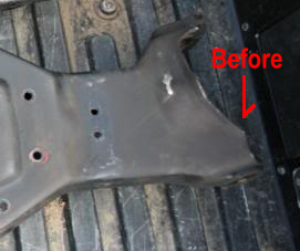
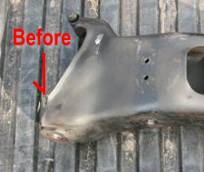
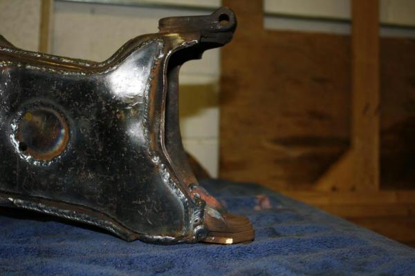
(Not the best photo, but gives you an idea of checking that the knuckle is 90-degrees. Knuckle should be turned straight forward.)
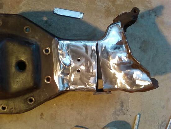
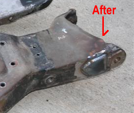
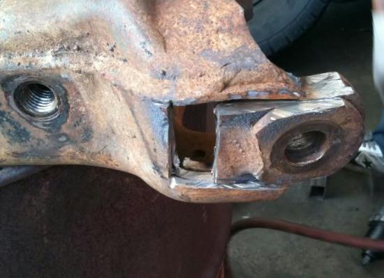
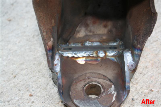
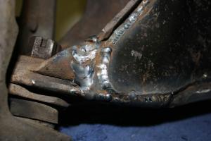
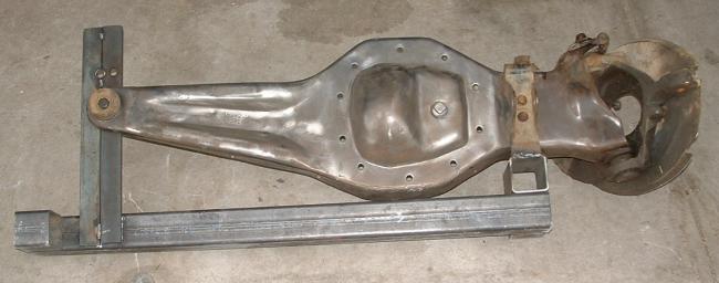
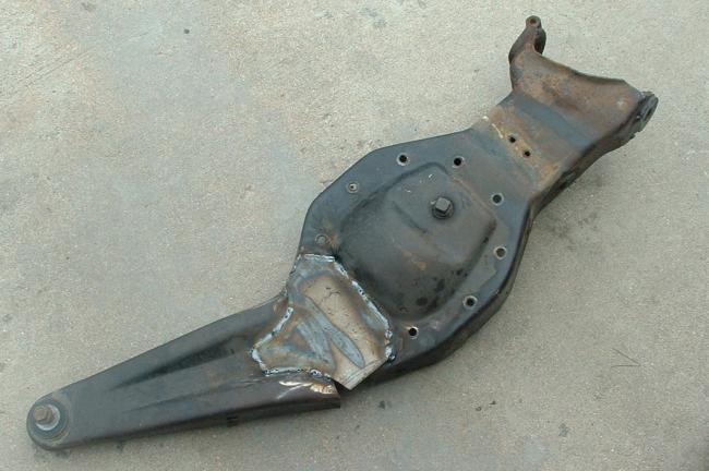
Here the beam is cut and the bottom of the knuckle is pushed outward to correct the camber. You can see where a piece was welded on to hold it in its new position.
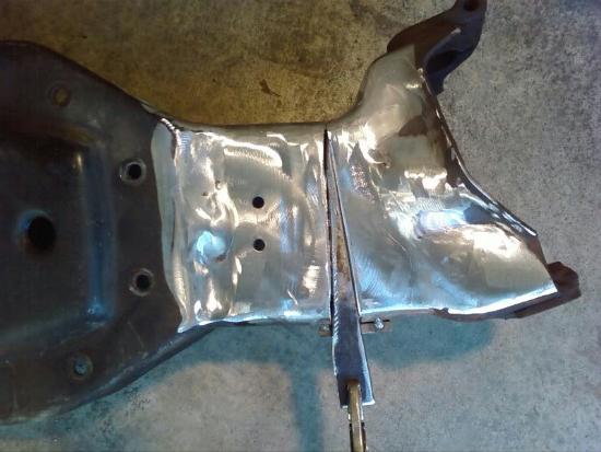
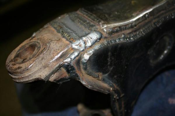
The gap is filled and then welded.
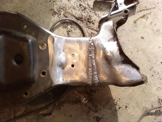
And then ground smooth.
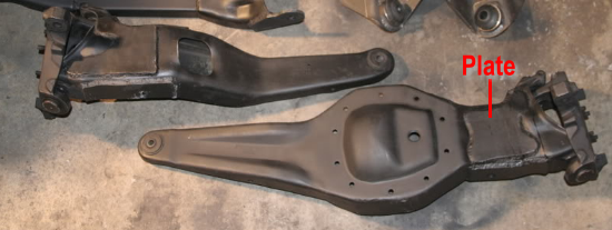
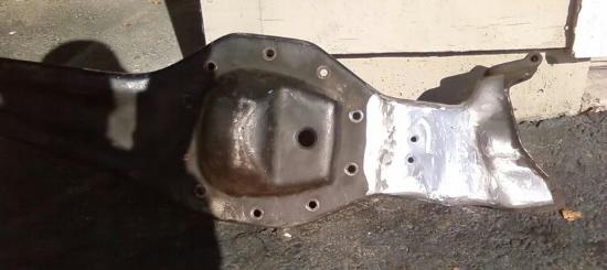
A metal plate is then welded over the cut and welded sections to strengthen them.
Using this method will not cause any significant reduction in your axle/track width.
Very important note: Cutting the beam and turning the entire knuckle up as described here creates a misalignment of the driver side axle shaft with the wheel spindle (see drawing below):
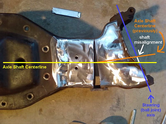
Two suggested ways to fix this are:
1. Reposition (“clock”) the differential on the beam slightly so that the shaft is realigned with the spindle (a pretty big job that requires reaming/redrilling all of the holes in the beam, along with modifying the pinch bolt support area at the rear), or:
2. Actually separating the driver-side knuckle from the beam, and moving it straight down approximately 1/4-1/2 inch so that the previous axle centerline at the knuckle will be aligned with the existing axle centerline where it crosses at the steering axis (pieces of 1/4-inch plate material can be aligned next to the gaps in the beam (top & bottom) that were created by moving the knuckle down and then welding them into place).
Be sure that you have checked for this issue before you fully weld up the beam (make sure that the axle shaft can be fully inserted into the diff and that it still rotates freely after you install the spindle).
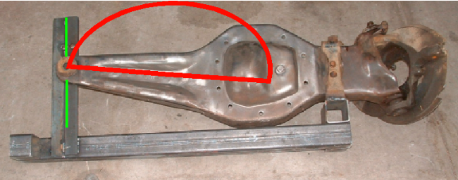
Cutting The Pivot End of The Axle Beam:
An early example of cut and turned beams were the ones done by Lee and Gloria Zimmermann on their 1993 Ford Explorer. This method involved creating a jig for cutting the pivot end from the beam, moving the mounting hole (pivot) up to compensate for the lift, and using material to fill in the gaps and strengthen it. This is probably the most difficult way to do a cut and turn, and is a method we do not recommend as it offers only minimal benefits of a Cut and Turn while introducing most of it’s drawbacks (see note about it’s disadvantages at the end of this article). Most, if not all, reputable race shops use the ball joint relocation method of modifying the beams.
The Zimmerman’s build can be found HERE for anyone wishing to reference it. It’s not exactly straight forward because they still used an axle beam drop bracket, and modified coil spring bucket.
Cutting and turning the axle beam on the pivot end will actually shorten the beam if steps aren’t taken to account for this.
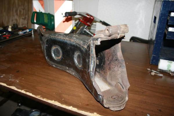
These (2) photos of the jig used by Bronco II owner 410Fortune shows how the beam becomes too short when the pivot is cut and repositioned for lift.
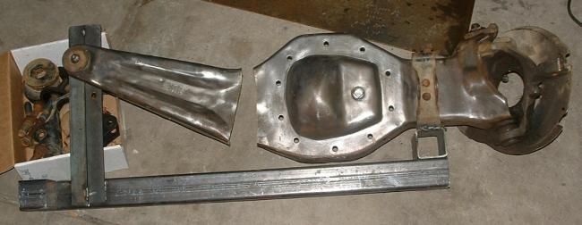
The drawing below gives you some idea of how the beam moves away from the mounting point if you turn the beam upward for lift. if you simply cut the beam and bend it, it will be to short. You actually have to cut it off and fill in the missing material.
If done using a jig like shown above, a significant reduction of your axle / track width can be avoided.
How Much Lift You Can Cut For:
A Cut and Turn is best suited to no more than 3-inches of increased lift height (5 inches if doing a Cut & Turn on a Dana 44 TTB). Users have reported issues with taller amounts of lift ranging from too much angle on the u-joints causing binding and/or bad vibrations while in 4WD, to issues with the RH axle slip spline overcompressing and/or overextending. Above 3 inches of lift (5 inches on a D44), drop brackets should be used in conjunction with the cut and turn so that the u-joint angles don’t become too extreme.
During 1987 and 1988, the Ford Ranger ‘High Rider’ STX offered a unique suspension with 1.5 inches more ground clearance. To accomplish this, Ford used different mounting brackets for the axle beams and radius arms. These brackets can be used with a Cut and Turn to provide an additional 1.5″ or so to the finished suspension.
Below is a photo of the STX brackets on the left, compared to standard brackets on the right.
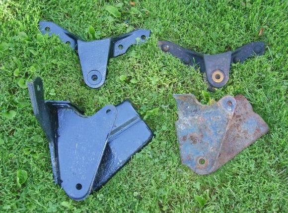
(1987-1988 Ford Ranger STX mounting brackets on the left – stock brackets on the right)
Clocking (Re-Indexing) The Differential (Cutting The Ball Joint & Cutting Before The Knuckle Methods):
If you angle the beam too far trying to factor in too much lift, you may have to re-index the differential on the beam. Otherwise, your driver side axle could point down too far, and the passenger side, up too far. This issue can come up with lifts of 5-inches or more on the Dana 35 TTB. This can be corrected by re-indexing (turning) the differential housing (requires various amounts of reaming, and/or redrilling of the holes in the beam), however you should avoid finding yourself in this position by keeping your lift height increase to 3 inches or less.
Use of the ‘Cutting Before the Knuckle’ method alone may also require re-indexing the differential for proper axle shaft alignment.
What are the disadvantages of a Cut and Turn on a TTB suspension?
Cut and Turning of a TTB effects big changes in the suspension’s geometry. While these changes give you significant additional clearance under your axle, a side-effect from it is an increased jacking moment that is created by the axle’s pivot points being higher up under the chassis relative to the axle. Another is an increased change in the track-width as the suspension cycles up and down. These effects normally don’t create much problem driving at high speeds, however they do have a potential to cause greater vehicle instability at slower speeds if the suspension unloads while on a steep off-camber hill or while rock crawling on a trail. For this reason, a Cut and Turn is a modification that is best suited to desert (prerunner) rigs that are built for higher-speed use.
Resources:
Be sure to check out our:
Ford Ranger 4×4 Suspension Forum