Submitted by Craig Evers
One of the least appreciated components in your fuel injection system is the fuel pump inertia switch.
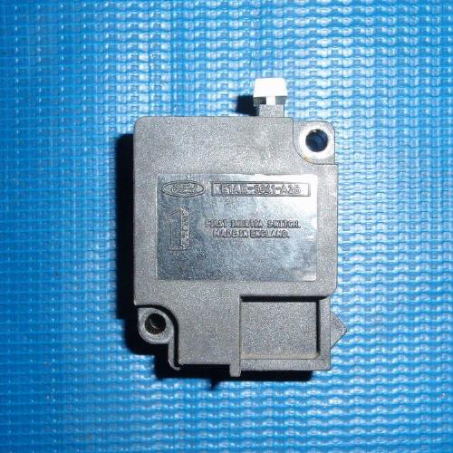
This little black box is designed to function flawlessly forever (or close to it), so it’s easy to forget it’s there. Its purpose is to shut off the fuel pump(s) in case of an accident, thus preventing fuel from being pumped all over the vehicle if there is a leak in the system. This obviously is a worthwhile thing to do, and one less thing to worry about if you are hanging from your seatbelt with your wheels in the air!
But what happens if this switch goes bad on you? How will you know, and how can you figure it out?
In my case, the switch went bad slowly over a period of months. It was exceedingly frustrating, and not just a little bit expensive, too! I got to meet a lot of nice wrecker drivers.
I was glad (for once) that the company had hung a cell phone on me as I sat at the side of an Iowa freeway watching a beautiful sunset over the snow-covered fields, with a strong wind rocking my Bronco II at -20° F! I had been driving along, listening to tunes on the radio, enjoying life when the engine died. No warning. Dead. Just like I had turned the key off. The only sound was 4 Goodyear GSAs whining down as I coasted to the side. We replaced the high pressure fuel pump that time, and the next time, when it died in a parking lot, we replaced the filter. The next time, as I was pulling into a parking space 20 miles from home, it did the same thing. As I sat waiting for my wife to come get me, I heard a “click” that I couldn’t place. I tried the key, it fired right up, and I drove home with no problems. I heard that “click” one other time, and it ran after, too.
When it would run, it ran fine. When it wouldn’t, there was nothing. Eventually, one day in the spring when it did it again in the parking lot at work, I did some thinking. The only things needed for the engine to run are compression, fuel, and gas. I can’t think of a self-healing condition related to compression that could give me the symptoms I was having. I had spark, as shown by the use of a spark tester. That left fuel. I cranked, and it wouldn’t fire, so I popped the hood and checked system fuel pressure. There is a little test port on the fuel rail that resembles the inflation stem of an inner tube for a bicycle tire. If you take off the cap, and push on the stem in the middle of the tube, you should get a squirt of gas if there is pressure. I got nothing, proving that the pump was not working. There was plenty of gas in the tank, but the pump wasn’t getting it to the engine.
I went under the back end to see I could confirm my diagnosis. While my wife cranked, I tried to feel any pump vibration or noise. Nothing! The ’88 Bronco II has a low pressure pump in the tank, and a high pressure pump on the frame rail. Both of them were dead. This is good. If one was dead, I’d have to replace a pump, but if they’re both dead, it means there is an electrical problem upstream from them.
I spent some time with the EVTM (Ford’s Electrical and Vacuum Troubleshooting Manual. If you don’t have one for your model and year, get one! It is well worth it to have every circuit in the truck diagrammed and explained in considerable detail.) Looking at the fuel system, there was a pump relay, the inertia switch, and a few connectors. It didn’t take much time to prove that the relay was good and the connectors were hooked up. That just left the FPIS (fuel pressure inertia switch), which is located under the dash in the passenger foot area, just at the front edge of the carpet. I pushed the RESET button on top of it, and the motor cranked right up and ran like it was supposed to. I drove straight to my local McParts store, and was told that the FPIS is a “dealer only” part. When I went back out, it wouldn’t start. Finally I held the RESET button down while my wife cranked, and it started. At home, it wouldn’t start again, no way, no how, so I jumpered it out by unhooking the connector and sticking a piece of wire in it across the two terminals. This is good enough to get to the dealer for a new one, or to limp home in an emergency, but it’s not a good idea to drive without the protection the FPIS gives you in an accident. Since I replaced the switch, I have had no more problems with this truck. The new switch was $40-.
So how does this switch work? Because I’m an engineer, and curious by nature, I did an autopsy, and took a few pictures of the workings of this part. It’s a neat piece of engineering. Somebody put a lot of thought into it. Hopefully you won’t have the same type of problem I had with it, but just in case you’ve been wondering about it, here’s how it works.
Switch Requirements:
The switch is designed to open when a sudden acceleration is experienced by the vehicle. This could be the result of hitting an object, such as another vehicle, a tree, or a wall. It could be the result of the vehicle rolling over, as into a ditch or off a road shoulder (or worse!) It must stay closed at all other times, even when bouncing along an ugly logging road or over potholes in a paved road. If it activates, and the vehicle is still drivable, it must be easily resetable so that you can drive away from there. It should never open otherwise (this is where mine let me down!)
Switch Design:
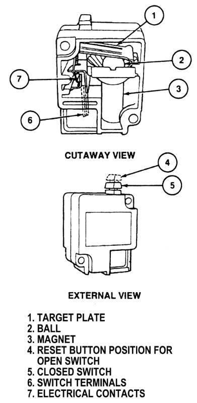
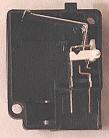
Internally, the switch is very similar to a relay. It has a couple of contacts that hook to the connector in the vehicle wiring. One is for power coming in, the other is for power going out to the pumps. In this picture, you can see that the switch is closed. The circuit is complete, and the pumps will run.
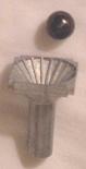
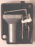
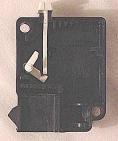
Instead of the electric solenoid coil or thermal expansion device that a relay uses to break the circuit, this switch uses a mechanical element consisting of a steel ball in a funnel. The ball is held in place by a magnet at the bottom of the funnel. When subjected to the design shock forces, the ball will break away from the magnet and roll up the side of the funnel, hitting the arm of the switch mechanism.
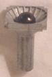
In this picture, the funnel is lying on its side, but the ball is held in by the magnet. When I examined the ball closely, I could see marks on its surface where it had been rattling around loose for some time. Evidently, my magnet wasn’t as strong as it had once been. This is a rare failure, but that doesn’t make it any less frustrating when you’re driving home in a wrecker!
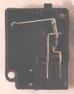
Here is the switch circuitry in the closed (operating) position. The long arm that reaches off to the left is connected by a spring to a short arm that pushes against the right contact. In addition to being part of the circuit path, the left contact provides a fulcrum to lever the long and short arms. The two holes in the housing are for the mounting screws that hold it to the vehicle body.
When the ball pushes against the bottom of the long arm, it moves it up, and the linkage moves the short arm, opening the circuit and cutting off power to the pumps. The circuit then stays in the open position until reset. The linkage is designed to be stable in either the open or the closed positions. In my switch, I found some signs of arcing on the faces of the contact surfaces between the right contact and the short arm, similar to the arcing on a set of ignition points in a distributor. This indicates that there had been a marginal connection, with vibration causing the two surfaces to move apart slightly, for some time.
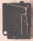
The white arm is the reset arm. It presses against the spring to move both the long and short arms back into position.
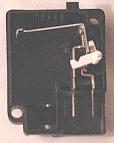
Here the reset arm has pushed the linkage back into operating position. Note that the notched end of the reset arm is lower in this position.
This is the other side of the switch housing, showing how the reset button engages the notch in the reset arm. When the button is pushed down, the top part of the reset arm pushes the spring to the right (because this is the other side of the housing, that would be to the left in all the previous pictures.)
So there it is. The ball sits in the cup, held in place by the magnet, until a shock hits it. The ball breaks free, rolls out of the funnel, and pushes the long arm up, then rolls back to the magnet and waits for the next time. The linkage of the long arm, spring, and short arm causes the short arm to move away from the contact, breaking the circuit and turning off the fuel pumps. Pushing on the reset button (which is white on this switch and red on the replacement) causes the linkage to reset itself.
SO If you are ever in an accident, or come hard off a jump, or do something else that puts a shock into the switch, your truck will probably die and it won’t start afterwards. Push the RESET button on your inertia switch, and you’ll probably be ready to roll again. For hard off-road use, you may want to replace this switch with a conveniently placed toggle switch that performs the same function, but won’t open when it takes a solid hit. (It could also be an anti-theft device.) For normal street use, the factory design is pretty good. I’m keeping it, even though it caused me so much hassle. Now that I know about this, and I have a new one installed, I’m running my little Bronco II like I always wanted to.
Diagram: