• Welcome Visitor! Please take a few seconds and Register for our forum. Even if you don't want to post, you can still 'Like' and react to posts.

high school shop students need electrical help-Please


adsm08

Senior Master Grease Monkey
Supporting Member
Article Contributor
Ford Technician
TRS 20th Anniversary
Joined
Sep 20, 2009
Messages
34,623
Reaction score
3,613
Points
113
Location
Dillsburg PA
Vehicle Year
1987
Make / Model
Ford
Engine Type
4.0 V6
Engine Size
4.0
Transmission
Manual
2WD / 4WD
4WD
Tire Size
31X10.50X15


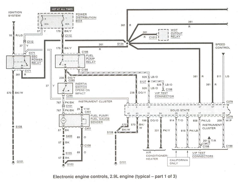
Ok, I will try to explain the relevant parts of this diagram. The section you need to worry about for starting the car pretty much runs down the left hand third of the page. Also, the page I linked is for 89+, which is arranged a tiny bit different than the 86 you are working on. The big difference is that instead of having a fuse block the power on your yellow wire will come from the stack of wires on the starter relay through a fused link.

Ford wiring diagrams generally follow the arrangement of power flows into the page at the top, and run through their loads to ground at the bottom of the page. That isn't really relevant to reading them, just helps finding things.

Your big yellow wire is connected directly to the positive battery cable on one end. The other attaches to the EEC power relay by a pin with two wires coming out of it. The second wire goes to the computer. That wire powers the "gate" of the relay. The piece that moves to close the circuit and power the load. On the other side of the gate should be a dark blue wire that turns red somewhere. It feeds power to two other pins on the computer and the fuel pump relay's coil. The computer then grounds the coil of the fuel pump relay to close it.

Power the the EEC relay's coil comes from a red/green wire that is switched on by the key. Then it looks like the coil should ground through your black and green wire. This is per my 87 wiring book. It looks like Ford may have changed some wire colors. So the black/white wire in the diagram I linked should be your black/green wire.

I am starting to think that your EEC relay has in fact been remove for some reason, as your first picture would seem to show the four wires going to it cut off. This would also mean you seem to be missing a yellow wire somewhere.


wildbill23c

Well-Known Member
U.S. Military - Veteran
TRS Banner 2012-2015
TRS 20th Anniversary
Ham Radio Operator
Joined
Aug 22, 2012
Messages
3,917
Reaction score
577
Points
113
Location
Southwestern Idaho
Vehicle Year
1987
Make / Model
Ford Ranger
Engine Type
2.9 V6
Transmission
Manual
2WD / 4WD
2WD
Total Lift
0
Total Drop
0
Tire Size
215/70-R14
My credo
19K, 19D, 92Y, 88M, 91F....OIF-III (2004-2005)
Not to hijack, but how many kids nowadays would even wanna learn how to wrench? Like it or not the automobile hobby is dying, which is sad really. Shop class in general teaches you alot of skills that can be applied elsewhere in other occupations and even life in general.
We still have an auto & ag shop here where I live, but the woodworking & welding shops are gone...well the stuff is still there at the high school, but nobody uses any of it, just sits there gathering dust. They claim they can't find anyone to teach those classes, but I'm pretty sure they just never bothered going out and trying to find anyone to teach those courses. I know of several people in town that would make awesome teachers so like I said I'm pretty sure they never tried to find anyone to fill those spots when the teachers retired about 7 years ago.
 

adsm08

Senior Master Grease Monkey
Supporting Member
Article Contributor
Ford Technician
TRS 20th Anniversary
Joined
Sep 20, 2009
Messages
34,623
Reaction score
3,613
Points
113
Location
Dillsburg PA
Vehicle Year
1987
Make / Model
Ford
Engine Type
4.0 V6
Engine Size
4.0
Transmission
Manual
2WD / 4WD
4WD
Tire Size
31X10.50X15
We still have an auto & ag shop here where I live, but the woodworking & welding shops are gone...well the stuff is still there at the high school, but nobody uses any of it, just sits there gathering dust. They claim they can't find anyone to teach those classes, but I'm pretty sure they just never bothered going out and trying to find anyone to teach those courses. I know of several people in town that would make awesome teachers so like I said I'm pretty sure they never tried to find anyone to fill those spots when the teachers retired about 7 years ago.
I can believe those are hard subjects to find teacher for in the public school system. Teaching in public schools has become a ridiculous cluster in most of the country, and those are two fields where you can make a lot more money in the private sector.
 

RonD

Official TRS AI
TRS Technical Advisor
Joined
Jun 2, 2012
Messages
25,363
Reaction score
8,370
Points
113
Location
canada
Vehicle Year
1994
Make / Model
Ford
Transmission
Manual
Nice project truck, I like to see old Rangers getting some love

There are 2 main relays and one optional relay on the inner fender

Brown Base relay is the EEC(computer) relay, it is controlled by key on/off
It powers the EEC, and the engine systems, like fuel injectors, spark, and a few sensors
Red wire out of the relay is that 12volt power, it should have continuity to any of the red wires on the fuel injectors, it you want to make sure you have the right red wire.

Green Base relay is Fuel Pump relay, it, of course, sends 12volt power to the Fuel pump power, it also has a Red wire that comes FROM the EEC Relays red wire, that red wire from the EEC relay has many splices and jumpers, i.e. 6 on the fuel injectors alone, lol.

Black Base relay, WOT(wide open throttle) relay, this was optional as it was used for AC(air conditioning), when driver pushed gas pedal to the floor(WOT) this relay would cut power to the AC Compressor giving driver all available engine power.
This relay also has a Red wire from the EEC relay lol.

adsm08 has the book so I would go by his wire colors

In your pictures I see what looks like the VIP or OBD1 connectors, Red connector with smaller grey connector next to it.
Nothing plugs into either connector, it is for testing and getting codes from EEC

Look here: http://www.therangerstation.com/how-to/ignition-charging-computers/testing-eec-iv-equipped-engines/

In the drawing the Fuel Pump slot in the connector is labeled, that is the GROUND for the fuel pump relay, if you jumper that slot to a Ground(key on) then fuel pump relay should "click" closed and send 12v to fuel pump(via inertia switch in cab).

But point is that the wire connected to that slot goes to Fuel pump relays ground, so red wire from EEC relay, and that color wire on VIP connector are the two wires for fuel pump relays coil
 

rockets

New Member
Joined
Mar 21, 2018
Messages
7
Reaction score
0
Points
0
Vehicle Year
1986
Make / Model
Ford
Transmission
Automatic
brown relay

To answer ADSM08,
There was a brown relay laying on the inner fender. We are pretty sure that's where the 2 red, yellow, and brown wire went. The mice had chewed that relay so far up that there was wire left so we could look at the color and match them up so we knew what wires went to what terminals. Thank you for the wiring diagram, I just don't know enough to hook the wires up going off that. I am trying to learn with the kids.
 

rockets

New Member
Joined
Mar 21, 2018
Messages
7
Reaction score
0
Points
0
Vehicle Year
1986
Make / Model
Ford
Transmission
Automatic
A/C

Also,
It does have A/C, but did not see any other relay.
 

alwaysFlOoReD

Forum Staff Member
TRS Forum Moderator
TRS Banner 2012-2015
TRS 20th Anniversary
Joined
Apr 13, 2009
Messages
13,941
Reaction score
5,086
Points
113
Location
Calgary, Canada
Vehicle Year
'91, '80, '06
Make / Model
Ford, GMC,Dodge
Engine Size
4.0,4.0,5.7
Transmission
Manual
2WD / 4WD
4WD

adsm08

Senior Master Grease Monkey
Supporting Member
Article Contributor
Ford Technician
TRS 20th Anniversary
Joined
Sep 20, 2009
Messages
34,623
Reaction score
3,613
Points
113
Location
Dillsburg PA
Vehicle Year
1987
Make / Model
Ford
Engine Type
4.0 V6
Engine Size
4.0
Transmission
Manual
2WD / 4WD
4WD
Tire Size
31X10.50X15
To answer ADSM08,
There was a brown relay laying on the inner fender. We are pretty sure that's where the 2 red, yellow, and brown wire went. The mice had chewed that relay so far up that there was wire left so we could look at the color and match them up so we knew what wires went to what terminals. Thank you for the wiring diagram, I just don't know enough to hook the wires up going off that. I am trying to learn with the kids.
I went back and double checked part descriptions/pictures. Ron D is correct about the relay colors, I had the EEC and WOT relays backwards. EEC is brown, WOT is black. WOT is still the only one with two solid red wires going to it. The EEC relay has a red/green and a dark blue wire coming off it that turns red down the line, according to the book. That part sounds suspicious to me, and make me wonder if the book has a typo.

I would look the red wires over carefully If you find one with a green line (it fades easily, you might have to dig into a taped section to find the tracer) then I would hook the other one to the relay.

If you relay connector has been chewed off so short that the wires can't be repaired I should have a connector that Id be willing to donate to the cause. I know I have a least one mostly complete 2.9 harness of the correct style.
 

rockets

New Member
Joined
Mar 21, 2018
Messages
7
Reaction score
0
Points
0
Vehicle Year
1986
Make / Model
Ford
Transmission
Automatic
working on it

Thank you for all your help thus far. I have printed off your comments and we will go through it today in class.
To help with some of the comments:
-The blower motor was taken out because there was a mouse city living in it. That would explain at least 2 of the wires. We have taped them off for now.
-I had the students cut the chewed ends of the wires to prepare for soldering and heat shrink. For those wandering why they are clean cut.
-Napa had a relay wire harness that we can wire in.
That's all for now.
Thank you, thank you, thank you
 

rockets

New Member
Joined
Mar 21, 2018
Messages
7
Reaction score
0
Points
0
Vehicle Year
1986
Make / Model
Ford
Transmission
Automatic
Running but......

Update.
Still can not figure out relay. I understand the concept, but can not make it work with the wires I have. I'm sure it's me not the wires.
Good or bad, I knew the yellow was hot all the time, and when it touches one of the red wires the fuel pumps turn on. Sooooooo. I held the 2 red and 1 yellow, and grounded the 4th. The engine started and ran smooth!! It would not turn off by the key, so I had to disconnect the reds and yellow wire.
There was a lot of yelling and clapping and cheering. So much that the principal came down to see what was going on. He was also thrilled and gave high fives.
We live to try again on Monday.
Thank you,
Doug
 

alwaysFlOoReD

Forum Staff Member
TRS Forum Moderator
TRS Banner 2012-2015
TRS 20th Anniversary
Joined
Apr 13, 2009
Messages
13,941
Reaction score
5,086
Points
113
Location
Calgary, Canada
Vehicle Year
'91, '80, '06
Make / Model
Ford, GMC,Dodge
Engine Size
4.0,4.0,5.7
Transmission
Manual
2WD / 4WD
4WD

adsm08

Senior Master Grease Monkey
Supporting Member
Article Contributor
Ford Technician
TRS 20th Anniversary
Joined
Sep 20, 2009
Messages
34,623
Reaction score
3,613
Points
113
Location
Dillsburg PA
Vehicle Year
1987
Make / Model
Ford
Engine Type
4.0 V6
Engine Size
4.0
Transmission
Manual
2WD / 4WD
4WD
Tire Size
31X10.50X15
Alright. I'll call that progress. You have shown that getting the EEC relay wired back into the system is really all that is needed to make it run.

The reason you couldn't shut it off with the key is that you had bypassed the relay, and by doing do you took the ignition switch on the column out of the circuit.

The basics of a relay are pretty simple. You have a coil and a gate. The gate controls the load the relay is there to control. The coil controls the gate.

Usually the gate always has power available on one end, in this case your yellow wire. The other end is hooked to the load to be controlled, in this case your engine computer, and your fuel pump relay.

The coil has one side grounded and the other side receives switched power, in this case from the ignition switch.

When the coil has power and ground it creates a magnetic field and draws the gate toward it, closing a set of contacts, and turning on whatever load you intend to operate.

Jumping the two wires together like you did (not really a bad way to do it) removed the coil from the circuit, so the key had no ability to shut the relay off, because you were the relay.

I will dig through my boxes of harnesses and see if I can't get you a picture of what your relay connector should look like.

You do still need to identify the wire coming from the ignition switch to the coil.
 

adsm08

Senior Master Grease Monkey
Supporting Member
Article Contributor
Ford Technician
TRS 20th Anniversary
Joined
Sep 20, 2009
Messages
34,623
Reaction score
3,613
Points
113
Location
Dillsburg PA
Vehicle Year
1987
Make / Model
Ford
Engine Type
4.0 V6
Engine Size
4.0
Transmission
Manual
2WD / 4WD
4WD
Tire Size
31X10.50X15
Ok, so I found my spare harness and took a look tonight.

There are 5 cavities and five wires on the bottom of the relay plug.

One cavity is blank, another has two wires.

If you hold the plug so the row of three cavities runs up and down the left side all three of those will have wires, as will the one at the top right (so the wires will make a backwards 7).

At the top two spots going across you need the yellow wires and the solid red wire.

The two lower spots on the left get the red/green wire and the black/green wire.

Which is which between the pairs doesn't matter too much since relays are non-directional, it just matters that the right wires are hooked to the right component inside the relay. This is true of 4-pin relays like this. It is less true of 5-pin relays.

Now to the issue of identifying the red/green wire vs the solid red, since the pictures seem to show your tracer is faded too badly.

Find the solid red wire at the fuel pump relay. It's the only red wire at the fuel pump relay. Ohm test it back to the two red wires you have at the EEC relay. One will show continuity, the other will show open. The one that shows open is your red/green wire.


If you are uncertain which pins are which on the relay you can do the same thing. Ohm test the pins to each other. With the relay off only two of them will show any continuity, those two are your coil and get the black/green and red/green wires.


Last edited:

RonD

Official TRS AI
TRS Technical Advisor
Joined
Jun 2, 2012
Messages
25,363
Reaction score
8,370
Points
113
Location
canada
Vehicle Year
1994
Make / Model
Ford
Transmission
Manual
The two Red wires on Brown relay probably go to the same contact of that relay, the power OUT of the relay
 

Sponsored Ad


Sponsored Ad

Staff online

Today's birthdays

Member & Vendor Upgrades

For a small yearly donation, you can support this forum and receive a 'Supporting Member' banner, or become a 'Supporting Vendor' and promote your products here. Click the banner to find out how.

Truck of The Month


Shran
April Truck of The Month

Recently Featured

Want to see your truck here? Share your photos and details in the forum.

Follow TRS On Instagram

TRS Events

25th Anniversary Sponsors

Check Out The TRS Store


Sponsored Ad


Sponsored Ad

Sponsored Ad


Amazon Deals

Top