• Welcome Visitor! Please take a few seconds and Register for our forum. Even if you don't want to post, you can still 'Like' and react to posts.

Not a wire guy


bobbywalter

TRS Technical Staff
TRS Event Staff
V8 Engine Swap
TRS Technical Advisor
TRS Banner 2012-2015
TRS 20th Anniversary
Ugly Truck of Month
TRS Event Participant
Joined
Aug 9, 2007
Messages
23,470
Reaction score
4,668
Points
113
Location
woodhaven mi
Vehicle Year
1988
Make / Model
FORD mostly
Engine Type
V8
Engine Size
BIGGER
Transmission
Automatic
2WD / 4WD
4WD
Total Lift
sawzall?
Tire Size
33-44
My credo
it is easier to fix and understand than "her"
I have removed the wires going to the so called (NSS) and put the jumper wire in so it still starts up with the clutch pressed in. And I found the to wires that run the reverse lights and now they work. So now I'm getting somewhere I think. Now I have the 2 wires coming from the (NSS) that I need to find a home for. And I only have one more spot to plug a wire in to on the plug. That wire is red w/white stripe on the other side of plug on the fender. I'm guessing that I will game to tie one those two wires from (NSS) to the reverse light wires and the other wires plugs in to the red w/white spot on fender plug. I THINK! But don't want to burn any wires up till I get another opinion
so for sure you have power to the unit and switch? no bad fuses and such?

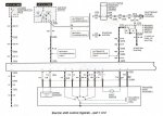
on this style I have always been able to get high range with nothing hooked up on the pedel or the trans so I am not sure where the issue is.. low range needed the switch to gd so you can go in and out...and the vss of course is there to keep it from exploding into low at a bad moment.

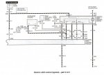
is there anything on this diagram you don't understand?? the module has a switch side and the motor side...with the power and inputs. the switch side confuses me....I see it as a p/g setup to turn off the abs in low...but looking at the harness it crosses my eyes pretty good:icon_twisted:


so I prefer levers....and manual operation. though my b2 has this setup.
 

Attachments

Last edited:


Fordfreak11

New Member
Joined
Dec 3, 2017
Messages
20
Reaction score
1
Points
0
Vehicle Year
91
Make / Model
Ford ranger
Transmission
Manual
I appreciate all the feedback. Bobbywalters I can read the wire color but for what ever reason I can't get it to register on what wires match up with each other on a plug. Kind of like it you unhook a plug and your looking at both side and you see a white wire on left side then you should be able to look at other side of plug and see what color it is plugged in to and Trace that down to where it goes. Looking at this I understand the wire color and kind of where they go but I see them numbered on one side of the square box and on on the other side of box numbers don't match or line up so not sure what wire goes to what. Sorry if I'm not making sense but that's kind of how i in confused.
 

bobbywalter

TRS Technical Staff
TRS Event Staff
V8 Engine Swap
TRS Technical Advisor
TRS Banner 2012-2015
TRS 20th Anniversary
Ugly Truck of Month
TRS Event Participant
Joined
Aug 9, 2007
Messages
23,470
Reaction score
4,668
Points
113
Location
woodhaven mi
Vehicle Year
1988
Make / Model
FORD mostly
Engine Type
V8
Engine Size
BIGGER
Transmission
Automatic
2WD / 4WD
4WD
Total Lift
sawzall?
Tire Size
33-44
My credo
it is easier to fix and understand than "her"
not sure if this will work for you, but I use this or a hard book when possible.


if it opens the page for you, I think you will get it figured out quickly.


https://www.scribd.com/document/9719562/93-Explorer-Elec-Transfer-Case-Shift-Diagnostics


The obvious first step in diagnosing a dead system is to check the POWER SOURCES, FUSES AND GROUNDS. If these check out, perform the
Shift Control Module Diagnostic Test. The illustration shows the Module with pigtail
A, B and C
attachments. The Diagnostic Test button and
Diagnostic Test LED are located on the side of the Shift Control Module.
1.DISCONNECT the
B and C connectors
, turn ON the ignition and allow
4 seconds
for the Module to power up.
2.Then PUSH the Diagnostic Test button.
a.If the LED
doesn't illuminate
, the Module is dead and must be replaced.
b.If the LED
comes on and stays on for 30 seconds
, there is an error condition and the module will have to be replaced.
c.If the module is OK the LED will
flash 4 times
.
This test, however, is not 100 percent accurate. During the test, the vehicle isn't operating, so the Shift Control Module isn't receiving data and
initiating shifts. If the unit
passes
the Diagnostic Test, it's probably a good Module. Check for other probable causes, although the Module may need
to be replaced even after passing the Diagnostic Test.
 
Last edited:

ericbphoto

Overlander in development
TRS Event Staff
TRS Forum Moderator
Supporting Member
U.S. Military - Veteran
TRS 20th Anniversary
VAGABOND
TRS Event Participant
GMRS Radio License
Joined
Feb 7, 2016
Messages
15,334
Reaction score
16,593
Points
113
Age
59
Location
Wellford, SC
Vehicle Year
1993
Make / Model
Ford Ranger
Engine Type
3.0 V6
Engine Size
3.0L
Transmission
Manual
2WD / 4WD
4WD
Total Lift
6"
Tire Size
35"
My credo
In theory, theory and practice are the same. In practice, they are different.
Looking at this I understand the wire color and kind of where they go but I see them numbered on one side of the square box and on on the other side of box numbers don't match or line up so not sure what wire goes to what.
ok.

looking at the diagrams above, you will see places where a wire stops and restarts with a number next to it like "C202". These numbers seem to always be to the righ of the wire or wires they refer to. This is a connector (plug) somewhere in the wiring. The wire color is labeled on each side of each connector. Also, along the box representing the 4x4 control module, you will see wires connected to the box with connector numbers to the right of them. Sometimes a s a group. But there may be more than one grouping of wires for that connector. for example, look for all the wires that are in groups labeled "C204" or "C205" or "C206". Inside the box, at each wire, is a number. This is the pin number where that wire should be in the plug connecting to the module. If you look closely at the actual plug in the truck, you may see a number next to the hole for each pin. Or you may just see a number 1 at one pin and anumber corresponding to the last pin at the last pin. for example, an 8-pin connector may only have pins one and 8 labeled. That helps you determine how the pins are labeled. Sometimes the numbers may go clockwise/counterclockwise around the connector. Sometimes they alternate with odd pins on one side and even on the other.

Since you have mixed and matched harnesses from different vehicles, you need to figure out for yourself how some of the connections need to be matched up. My recommendation would be to check each and every wire one at a time against the diagram and make sure you have a wire to represent every necessary connection for your configuration (manual transmission, if I recall?). Pay attention to the optional wires. You will not have a neutral safety switch. So your pink wire from the key switch will go to the "starting circuit" as shown in the diagram. I haven't looked. but I bet that will go to the clutch switch and then on to something else in the starting circuit. That is on another diagram. That same pink wire also goes to C202 and becomes a red wire with light blue stripe on the other half of the connector. then it goes to the control module.

This can be a tedious process. But, luckily, this is a simple system in a simple vehicle. Take your time and do it. You will be thankfull in the end if you make sure everything is right.
 

bobbywalter

TRS Technical Staff
TRS Event Staff
V8 Engine Swap
TRS Technical Advisor
TRS Banner 2012-2015
TRS 20th Anniversary
Ugly Truck of Month
TRS Event Participant
Joined
Aug 9, 2007
Messages
23,470
Reaction score
4,668
Points
113
Location
woodhaven mi
Vehicle Year
1988
Make / Model
FORD mostly
Engine Type
V8
Engine Size
BIGGER
Transmission
Automatic
2WD / 4WD
4WD
Total Lift
sawzall?
Tire Size
33-44
My credo
it is easier to fix and understand than "her"
theres other potential problems with the the hidden "c202" type circuit connectors where wires splice and change colors as he mentioned as well....

like some are diode protected and the asshats never mention it. so you put power to something like it plainly appears you are supposed to do and the next thing you know your repairing a trace that you burned up on a board or buying a new controller or whatever....:shok:

you pull a few harness apart when building custom stuff and you really pick up more perspectives.

in this case the manual/auto trans option lil two color circuit wants ground to work....red/blue or red white....not sure if these specific controllers are a "bothy" like some of the auto pcms...never learned that for sure. i have seen key on issues before so i assumed they were able to get a signal beyond 5v ref....
 

Fordfreak11

New Member
Joined
Dec 3, 2017
Messages
20
Reaction score
1
Points
0
Vehicle Year
91
Make / Model
Ford ranger
Transmission
Manual
Thank guys I'm going through the wiring hopefully this weekend and hope to return with some good news. But wiring is definitely my weekness. By far.
 

Fordfreak11

New Member
Joined
Dec 3, 2017
Messages
20
Reaction score
1
Points
0
Vehicle Year
91
Make / Model
Ford ranger
Transmission
Manual
Ok guys I printed out that diagram and put wires to where I thought they belong after testing all of them. And double checked fuses inside and under the hood. And now my 4x4 works!!! I'm not sure exactly what fixed it but I'm sure putting wiring where it belongs did the trick. Thanks for dealing with and melt down and being helpful with info guys. Thanks again to all.:yahoo::icon_hornsup::beer::beer::icon_idea:
 

ericbphoto

Overlander in development
TRS Event Staff
TRS Forum Moderator
Supporting Member
U.S. Military - Veteran
TRS 20th Anniversary
VAGABOND
TRS Event Participant
GMRS Radio License
Joined
Feb 7, 2016
Messages
15,334
Reaction score
16,593
Points
113
Age
59
Location
Wellford, SC
Vehicle Year
1993
Make / Model
Ford Ranger
Engine Type
3.0 V6
Engine Size
3.0L
Transmission
Manual
2WD / 4WD
4WD
Total Lift
6"
Tire Size
35"
My credo
In theory, theory and practice are the same. In practice, they are different.
Congratulations! The project you did was complicated. It's easy to get confused a little bit. Glad you got it worked out.

Sent from my SM-G920V using Tapatalk
 

Sponsored Ad


Sponsored Ad

Staff online

Member & Vendor Upgrades

For a small yearly donation, you can support this forum and receive a 'Supporting Member' banner, or become a 'Supporting Vendor' and promote your products here. Click the banner to find out how.

Truck of The Month


Shran
April Truck of The Month

Recently Featured

Want to see your truck here? Share your photos and details in the forum.

Follow TRS On Instagram

TRS Events

25th Anniversary Sponsors

Check Out The TRS Store


Sponsored Ad


Sponsored Ad

Sponsored Ad


Amazon Deals

Top