• Welcome Visitor! Please take a few seconds and Register for our forum. Even if you don't want to post, you can still 'Like' and react to posts.

Camshaft Syncro Position and TDCC


Rearanger

Active Member
Joined
Feb 4, 2008
Messages
1,429
Reaction score
23
Points
38
Location
Southeast USA
Vehicle Year
2003
Make / Model
Ford
Transmission
Manual
Doing my camshaft syncro and sensor.

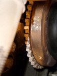
Setting TDC so that the zero mark on the harmonic balancer (fifth tooth to left of gap) is centered on the crankshaft position sensor (between edges of flat spot). Then looking at trigger finger it should be centered in the gap of the syncro.

However, it was not. The finger was just off left of the gap. I had to move the TDC CW some more so that the finger was centered in gap - that's the only way the alignment tool will fit. That put the zero mark at the 12 o'clock position of crankshaft rotation. But there seems no corresponding engine mark there.

Question then is where the hell is the TDC mark on engine? The zero mark tops out at the top of the crankshaft rotation when the syncro finger is centered. All I can see is what looks like a corresponding TDC mark behind the crankshaft position sensor on the front cover.

Syncro is factory original and has never been moved.

Thanks for any clarification.


JP02XLT

Member
Joined
Nov 23, 2008
Messages
466
Reaction score
8
Points
18
Location
Indiana
Vehicle Year
02
Make / Model
Ranger
Engine Size
3.0
Transmission
Automatic
According to the factory specs the line in the harmonic balancer should line up with the line on the cover you found. The only true way to tell is a degree wheel & piston stop to find absolute TDC.

The factory marks do not account for any of the slop in the timing chain, so that could explain the CPS being a little off in relation to the crank.

JP02XLT
 

Rearanger

Active Member
Joined
Feb 4, 2008
Messages
1,429
Reaction score
23
Points
38
Location
Southeast USA
Vehicle Year
2003
Make / Model
Ford
Transmission
Manual
According to the factory specs the line in the harmonic balancer should line up with the line on the cover you found.
I searched but could not find any reference in my FSM, it's not a user friendly design. It seems the only way to see "the line" on the engine is to remove the crankshaft position sensor, which I did not do. I can just see the line with struggle behind the sensor. But sighting it at the mid line of the sensor does not get the trigger finger of the syncro near close enough.

The factory marks do not account for any of the slop in the timing chain, so that could explain the CPS being a little off in relation to the crank.
Well the chain stretch would have to be quite severe to account for the difference and I should think I'd notice timing problems?? The only way to prove would be pull the front cover - not going to happen now.

Any thoughts on setting TDC with the marks then pulling the synco and realigning the trigger finger to the correct position on reinstall? The electrical timing would be moved by the degrees from the TDC mark at the crankshaft position sensor to 12 o'clock position on crank.

I think I'll get my timing light out and check firing position for #1 and TDC.
 

JP02XLT

Member
Joined
Nov 23, 2008
Messages
466
Reaction score
8
Points
18
Location
Indiana
Vehicle Year
02
Make / Model
Ranger
Engine Size
3.0
Transmission
Automatic
I have the timing alignment info from a multi year Ford service manual set for the 3.0, I know what you mean about it being very vague, This is the only picture that I have seen referencing the timing marks, and your exactly right about not being able to see it.

When I rebuilt my 3.0 I marked the balancer and the mark with high visibility paint, it helps but the mark is still behind the balancer like you described, it almost takes a fair amount of Kentucky windage alignment with the eyeball to even get it close and see where your at.

As for re-positioning the sensor, the ECM has a window of Adjustment (for lack of better terms) that it will compensate for the sensor being out of position & still correct the timing. That is Fords way for everything else not needing to be perfect, just within tolerance.

So my feeling is if you adjust the sensor to the new alignment spot your likely to get a SES light on the dash with CPS code as well as a poor running vehicle as you may be out of the window of adjustment capabilities of the ECU. Did you adjust it with the tool?

I know on a Chevy with a similar setup you have about 4 degrees of rotation on the distributor (which they use as the cps) for a correct alignment of the unit, so that is a very small window of adjustment to hit, or you get a light on the dash and the CPS code.

While chain stretch is possible, your right it would take a fair amount of stretch to get out of alignment & it surely would be making some noise in the cover area.

Post back how you come out on this,

JP02XLT
 

Rearanger

Active Member
Joined
Feb 4, 2008
Messages
1,429
Reaction score
23
Points
38
Location
Southeast USA
Vehicle Year
2003
Make / Model
Ford
Transmission
Manual
Found reference to TDC and the teeth on the harmonic balancer to the crankshaft position sensor in my "Powertrain Control & Emissions" FSM. It shows the 6th tooth past the gap alignment as TDC (1&5) while I was using the 5th tooth from a description/picture on another forum.

The 6th tooth aligns with a "TDC" marking on the crankshaft pulley but is past the "zero" mark on the pulley. A note at the bottom of the page states:

"This diagram does not correlate to any timing marks that may be on the engine front cover or damper." The center of the gap is 60 degrees BTDC.

Maybe Adam or another tech will read this and contribute. I just put everything back together with old syncro and will do further research.
 

JP02XLT

Member
Joined
Nov 23, 2008
Messages
466
Reaction score
8
Points
18
Location
Indiana
Vehicle Year
02
Make / Model
Ranger
Engine Size
3.0
Transmission
Automatic
Nice information, I did mine by a degree wheel when it was out but there is almost no way you could do it like that with the engine in the truck, unless you removed the radiator, & most of the front end

JP02XLT
 

Rearanger

Active Member
Joined
Feb 4, 2008
Messages
1,429
Reaction score
23
Points
38
Location
Southeast USA
Vehicle Year
2003
Make / Model
Ford
Transmission
Manual
I did mine by a degree wheel
Where was the TDC mark on the engine, under the crankshaft position sensor?

Cause if that's it I'll remove the sensor to get the syncro lined up.
 

JP02XLT

Member
Joined
Nov 23, 2008
Messages
466
Reaction score
8
Points
18
Location
Indiana
Vehicle Year
02
Make / Model
Ranger
Engine Size
3.0
Transmission
Automatic
facing the engine, just to the right of the Crank position sensor, there is a lug on the front case, on the front of that lug is a line in the center of the lug, it is only on the face of the lug (facing towards the front of the truck) On my motor true TDC, the balancer algined very closely to this mark, that is what I aligned too, and use as my TDC reference yet today. The mark on the casting is a royal pain to see as it is not present on the upper surface of the lug. Not sure if removing the Crank sensor will help you see this mark or not, as it too is behind the balancer. Why they went to the trouble of having alignment marks on these 3.0's when you cant see them is beyond me.


JP02XLT
 

Rearanger

Active Member
Joined
Feb 4, 2008
Messages
1,429
Reaction score
23
Points
38
Location
Southeast USA
Vehicle Year
2003
Make / Model
Ford
Transmission
Manual
just to the right of the Crank position sensor, there is a lug on the front case, on the front of that lug is a line in the center of the lug
Yes thanks, that's what I see behind my CRK sensor as well. I'm going to remove the sensor and use that mark to set the syncro. Not going to worry about where teeth are on crankshaft for position sensor. I've already marked my crankshaft timing marks clearly with whiteout.

A description in my manual says syncro tells computer where mechanical TDC is. I think the factory got it close, but not exact. Maybe this will improve my slightly rough idle.
 

JP02XLT

Member
Joined
Nov 23, 2008
Messages
466
Reaction score
8
Points
18
Location
Indiana
Vehicle Year
02
Make / Model
Ranger
Engine Size
3.0
Transmission
Automatic
Let me know how you come out & if that improves your idle, you have such a small window to hit or like you thought the timing is off, will the ECU account for it being off & how close does it get your timing, that is the big question.

Glad you found the mark on the cover.

JP02XLT
 

det107

Active Member
TRS 20th Anniversary
Joined
Mar 3, 2011
Messages
1,333
Reaction score
23
Points
38
Location
Vails Gate, NY
Vehicle Year
2002
Make / Model
Ford
Engine Size
3.0
Transmission
Manual
Doing my camshaft syncro and sensor.
Were you getting any codes that prompted you to R/R part ? If so, what was the numbered codes-
 

JP02XLT

Member
Joined
Nov 23, 2008
Messages
466
Reaction score
8
Points
18
Location
Indiana
Vehicle Year
02
Make / Model
Ranger
Engine Size
3.0
Transmission
Automatic
P0340 is the CPS code, usually you get the squeaking before you get a code.

JP02XLT
 

Rearanger

Active Member
Joined
Feb 4, 2008
Messages
1,429
Reaction score
23
Points
38
Location
Southeast USA
Vehicle Year
2003
Make / Model
Ford
Transmission
Manual
Let me know how you come out & if that improves your idle
Today I attempted to replace - it was an adventure.

First the "zero" mark on the harmonic balancer IS aligned with the 5th tooth right edge (from gap), not the 6th as is shown in my diagnostic manual. Removing the CRK sensor allows you to see the tiny line on the engine lug and line up the zero mark on the balancer with it - with a friend's help.

Inspection of the old syncro shows no sign of wear. I think it's just the worn o-ring on the shaft that is causing the small oil leak. Inspection of the replacement Standard Auto part to the Ford OE part show they are identical except the Standard Auto has a slightly thicker oil pump shaft drive. BUT the story does not end here.

In the end I reinstalled the Ford OE because of two reasons. I found the reamed hex in the oil shaft drive in the Standard part was terrible quality. It had burrs and metal chips in it and I was able to break loose several chips - not good if they fell inside the engine.

Second the new part just would not go in all the way. As much as I tried I could not get the new o-ring into the bored hole, whereas the OE went in and out easily. There is some gear mesh clearance that does not cause binding, so that was not the reason. I don't think a new o-ring should be that hard to install (yes I used oil). Thought about using a wooden dowel and hammer but decided not to go that route, especially with the poor quality of the Standard part. It's going back to RockAuto.

Getting that 38* angle of installation is a real trial for first attempt. It either looks like 28* or 48* depending on which gear tooth you use - there is only two choices. Even using a small plastic protractor did not make it easier - but you definitely need some kind of angle reference. I reinstalled the OE part and the new part several times but the angle did not get any easier to see. I finally settled on the 28* number because that most closely matched the original sensor angle. Starting and driving showed I must have done it correctly because it ran fine with a good idle. I also used a timing light to proof out the position and it came dead on.

For those contemplating doing this I highly recommend referencing the sensor plug angle before removing the the old syncro. I had some doubts about my sensor trigger finger position to TDC so was starting from zero on installation so did not want a bad reference. For sure the trigger finger is now dead center in the syncro gap.

I wish I could buy new o-rings for the OE syncro, but I haven't tried looking yet.
Edit: Yes Ford has just the o-ring - $16.00 I guess I'll wait until the weep turns into a leak. NAPA does not list it.

Sorry for the long post.
 
Last edited:

Rearanger

Active Member
Joined
Feb 4, 2008
Messages
1,429
Reaction score
23
Points
38
Location
Southeast USA
Vehicle Year
2003
Make / Model
Ford
Transmission
Manual
Just thought I'd post a pic of timing marks. Crank sensor tooth is 5th from the gap. You can just see the line on the lug behind the crankshaft wheel.
 

Attachments

JP02XLT

Member
Joined
Nov 23, 2008
Messages
466
Reaction score
8
Points
18
Location
Indiana
Vehicle Year
02
Make / Model
Ranger
Engine Size
3.0
Transmission
Automatic
I am sure the O-ring is nothing special, find a good bearing supply house, we are small town and we have 2 of them around here, they usually have, or can get O-rings in any size, especially if you have the old one to match too.

Another venue is Mcmaster Carr, they carry o-rings as well, but will be a little pricey & you will have to do the measuring to determine what to order.

Glad you found the timing marks, my 07 balancer does not have the 0-10 degree marks, only the TDC mark. Either way they are a bear to find.

Nice picture of the timing marks, that will definitely help someone out in the future when they are looking for it.

JP02XLT
 
Last edited:

Sponsored Ad


Sponsored Ad

Staff online

Member & Vendor Upgrades

For a small yearly donation, you can support this forum and receive a 'Supporting Member' banner, or become a 'Supporting Vendor' and promote your products here. Click the banner to find out how.

Truck of The Month


Shran
April Truck of The Month

Recently Featured

Want to see your truck here? Share your photos and details in the forum.

Follow TRS On Instagram

TRS Events

25th Anniversary Sponsors

Check Out The TRS Store


Sponsored Ad


Sponsored Ad

Sponsored Ad


Amazon Deals

Top