• Welcome Visitor! Please take a few seconds and Register for our forum. Even if you don't want to post, you can still 'Like' and react to posts.

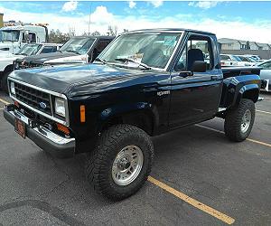
1988 B2 Conversion using 2000 Explorer 302


dSINtia

New Member
Joined
Dec 8, 2010
Messages
85
Reaction score
0
Points
0
Transmission
Automatic
Thanks SVT! Obviously still working through my plan (and learning). I'll go with the 180. Will I be able to utilize the B2's cruise system? I'll do a few searches and see what I can come up with...

On the block plates... These are original mounts from an 87-93 5.0L Mustang? If so, a set from Rockauto is under 20 bucks...


RangerSVT

Oct 09 OTOTM
Article Contributor
V8 Engine Swap
OTOTM Winner
Solid Axle Swap
RBV's on Boost
ASE Certified Tech
TRS Banner 2010-2011
TRS Banner 2012-2015
Joined
Mar 15, 2009
Messages
7,883
Reaction score
53
Points
48
Location
TRS since 2002 - NW KY
Vehicle Year
19962002
Make / Model
Ford
Engine Size
GT-40 5.0L EFI W/AC
Transmission
Automatic
The cruise control system does not use or rely on the ECU, so there is a very good chance you can use the original system. If your set on using the mustang mounts, 87-93 mustang convertible mounts are the ones that are used...

SVT
 

dSINtia

New Member
Joined
Dec 8, 2010
Messages
85
Reaction score
0
Points
0
Transmission
Automatic
Nope... Not set on anything Mustang. I'd prefer to use what you're recommending... The block plate mounts but I'm not sure what model vehicle from 87-93 years. I'm in no position to go my own way on this deal and I won't turn
down good, free advice... :)
 
Last edited:

RangerSVT

Oct 09 OTOTM
Article Contributor
V8 Engine Swap
OTOTM Winner
Solid Axle Swap
RBV's on Boost
ASE Certified Tech
TRS Banner 2010-2011
TRS Banner 2012-2015
Joined
Mar 15, 2009
Messages
7,883
Reaction score
53
Points
48
Location
TRS since 2002 - NW KY
Vehicle Year
19962002
Make / Model
Ford
Engine Size
GT-40 5.0L EFI W/AC
Transmission
Automatic
The plate style uses a flat plate that bolts to the engine and sets down on the stock ranger 2.9/ 4.0 rubber mounts. It allows you to drop the engine in once opposed to several times using the mustang mounts (one to mark the hole, pull the motor, drill hole for mustang mount, then lower motor back in truck, if not sitting right front to back, pull motor back out, re drill/enlarge hole, etc). The plate is slotted for easy adjustability without pulling the motor, it also retains stock original motor mounts for easy replacement wear items. Easy to make...

SVT
 

dSINtia

New Member
Joined
Dec 8, 2010
Messages
85
Reaction score
0
Points
0
Transmission
Automatic
This makes a lot of sense. I'll search the forums for info... I have access to a weld shop so fabrication won't be an issue if I can get a hold of some drawings...
 

dSINtia

New Member
Joined
Dec 8, 2010
Messages
85
Reaction score
0
Points
0
Transmission
Automatic
On SVT's advice, I've been looking for drawings or specifications for plate style motor mounts planning to build a set out of 3/8" steel and I ran across these:

http://www.summitracing.com/parts/aaf-all38112/applications/

For just $33 it seems easier for me to use if they are decent and will work correctly. Does anyone have any experience with these or similar plates? Will these work? Thanks in advance.

D2
 

dSINtia

New Member
Joined
Dec 8, 2010
Messages
85
Reaction score
0
Points
0
Transmission
Automatic
Sorry for the persistent questions but I got to thinking about the motor coming out of the donor. It is a relatively low mile 302 and ran great. It ran at temperature, didn't smoke or burn oil and had good oil pressure and I haven't noticed any leaks.

I have a stand and am not in a hurry to jump in to the B2, so why not take the opportunity to run through the engine to make sure it is good? What should I consider replacing? Keep in mind I am not after performance, just the durability and dependability expected of a stock motor.

I'm planning on doing valve cover gaskets, plugs, wires, hoses, t-stat and the belt but what else would you all recommend? Main seals? Oil pump? Injectors?

Appreciate the help...
 
Last edited:

RangerSVT

Oct 09 OTOTM
Article Contributor
V8 Engine Swap
OTOTM Winner
Solid Axle Swap
RBV's on Boost
ASE Certified Tech
TRS Banner 2010-2011
TRS Banner 2012-2015
Joined
Mar 15, 2009
Messages
7,883
Reaction score
53
Points
48
Location
TRS since 2002 - NW KY
Vehicle Year
19962002
Make / Model
Ford
Engine Size
GT-40 5.0L EFI W/AC
Transmission
Automatic
Dont think those plates will work. If your gonna pull the oil pan, high pressure pump is what id install, as well as check the ods and main bearings, crank end play, etc.rear main seal, timing cover seal, valve cover seals (basically, reseal the entire motor while its out) including freeze plugs...

SVT
 

dSINtia

New Member
Joined
Dec 8, 2010
Messages
85
Reaction score
0
Points
0
Transmission
Automatic
Thanks SVT.

I'll plan to do all of that... I'll be swapping on the dual sump and pickup anyhow so a high pressure pump will be super easy. Thanks!

D2
 

dSINtia

New Member
Joined
Dec 8, 2010
Messages
85
Reaction score
0
Points
0
Transmission
Automatic
So I've been working on cleaning and doing a soft rebuild on this motor and as I prepare to get it all wired up (remember I'm essentially converting it from a 2000 to a 1997 electronically) I come to the Camshaft Synchronizer and Camshaft Position (CMP) Sensor. The 2000 uses a 2-wire CMP sensor (sometimes referred to as a CKP or CPS) and the 1997 a 3-wire. Initial suggestions were that the CPS simply needed to be changed but after lots of research (always fun) I've learned that when converting to the 3-wire CPS it isn't as simple as swapping the sensor so I wanted to offer what I've gleaned in case someone else may be faced with similar issues...

Anyhow, the differences in the CPS and matching synchronizer are more significant than the number of wires. I've learned those wires actually do stuff... who knew? Anyways, both CPS are of the Variable Reluctance Synchronizer (VRS) type. The 2-wire CPS is used with a VRS whereas the 3-wire is used with the Hall-Effect VRS... the CPS' and synchronizers ARE NOT interchangeable as the signals produced are significantly different when compared to one another not to mention the rotating "vane" atop the block mounted synchronizer is of drastically different size and thickness when comparing the two. Both synchronizers produce A/C current. The VRS produces a standard speed-sensitive sine wave while the Hall-Effect produces a square sine wave, hence the use of three wires vice two. The VRS' vane is a single pole (interrupter) ~1/4" in width and 1/8" in thickness and the "Hall" has a larger but thinner "c-shaped" semi-circle vane approximately 1" in length and 1/16" in thickness.

I was forced to review all of this because once I learned I needed to swap my synchronizer (not difficult) I was confused by the differences I noticed when I was getting ready to remove the old and "stab" the new one... without the handy-dandy little tool. Again not too difficult, simply a matter of making a few marks and going at it but I wasn't sure where, in relation to the synchronizer vane I needed to mark... the middle of the vane, the leading edge of the vane, the back edge of the vane. The answer is this:

If you have to change from a VRS to Hall-Effect synchronizer and do not have the tool, mark the position of the synchronizer relative to the placement of the old one in the block and make a matching and corresponding mark on the replacement Hall synchronizer (be precise). Next bring the motor to TDC #1 cylinder (the VRS vane will align right in the middle of the "window") and make a mark on the block and synchronizer body relative to the center of the VRS vane (transpose this mark to the very same position on your new synchronizer) - you now have two marks on your block that will tell you where to land both the synchronizer body (already marked) and vane. Remove the old synchronizer and DO NOT rotate the motor. Your goal is to stab the Hall-effect synchronizer into the position that will leave the leading edge of the vane aligned with the "vane" mark you made previously on the body. Holding the new Hall-effect synchronizer in your hand, rotate the shaft counter-clockwise until the leading edge of the vane aligns with the mark you previously made being sure to hold the vane in place as you "stab" the synchronizer. Start ~15 degrees counter-clockwise from where you want to land the leading edge of the vane then you'll need to rotate the synchronizer clockwise ~15 degrees into the motor as it engages the teeth, being sure not to allow the vane to shift orientation. The body of the synchronizer can and will move... no biggie, just adjust it after your synchronizer is seated until the mark you made on the body lines up with the mark on the block. If all is done correctly, the synchronizer will look to be in the very position as the old one and the leading edge of the Hall-effect vane will line up with the mark you made on both the block and housing.

I'm sure in my head this all makes sense - if not, hell at least I have it for posterity. Maybe everybody already knew all of this stuff but I didn't and I'm betting someone else out there will have to deal with it at some point so here it is...

Or I guess you could just get the damn tool from OTC or SirTools... eBizzle has'em for $30.

Anyhow, I hope this helps someone...

D2
 

RangerSVT

Oct 09 OTOTM
Article Contributor
V8 Engine Swap
OTOTM Winner
Solid Axle Swap
RBV's on Boost
ASE Certified Tech
TRS Banner 2010-2011
TRS Banner 2012-2015
Joined
Mar 15, 2009
Messages
7,883
Reaction score
53
Points
48
Location
TRS since 2002 - NW KY
Vehicle Year
19962002
Make / Model
Ford
Engine Size
GT-40 5.0L EFI W/AC
Transmission
Automatic
I bought the syncro from rock auto and the alignment tool came with it...

SVT
 

dSINtia

New Member
Joined
Dec 8, 2010
Messages
85
Reaction score
0
Points
0
Transmission
Automatic
I looked into buying a new one as I knew the tool would come with it but MAC came through like a champ and sent me one with the a replacement 3-wire sensor. Both of you guys have been awesome... thanks!
 

dSINtia

New Member
Joined
Dec 8, 2010
Messages
85
Reaction score
0
Points
0
Transmission
Automatic
Okay...

To recap, I picked up a 2000 Ford Explorer with 60K on the clock. Over the last 9 months I've scored a new transmission (96), got a 96 ECU and wiring harness, changed sensors to work with the new ECU and harness, did a soft rebuild on the motor, got motor mounts and a two-speed Taurus fan, replaced the oil sump and pump and threw on a new water pump. Got the oil filter relocation kit and I've cleaned the motor up - a little bit. Bought all new fluids, plugs, hoses, etc... and extended my ECU pigtail. I'm ready to rock...

And then I get orders... part of the military life. I've sunk a lot of time and money into this project and to think it may have to wait another two years didn't sit well. So I contacted RangerSVT and have worked with him over the last few weeks.

Yesterday, I trailered the B2 and all of the parts to his place and he's going to do the swap for me. I won't discuss costs or payment but I asked that he post up a few pictures of the build as he goes a long and he agreed.

This truck has been in the family since new and was my wife's mother's before she passed of cancer in 94. My oldest was born in 95 and now it is his... We've talked about doing this swap for years and are incredibly excited to have it finally come to fruition.

I can answer questions about what I've done to prepare but I freely admit I am a novice learning so I hope RangerSVT can walk people through what he's done once he starts the build.

Can't wait to see progress... over to you RangerSVT.

(btw - I saw his Ranger (SVT) in person yesterday... what a BEAST!)
 

RangerSVT

Oct 09 OTOTM
Article Contributor
V8 Engine Swap
OTOTM Winner
Solid Axle Swap
RBV's on Boost
ASE Certified Tech
TRS Banner 2010-2011
TRS Banner 2012-2015
Joined
Mar 15, 2009
Messages
7,883
Reaction score
53
Points
48
Location
TRS since 2002 - NW KY
Vehicle Year
19962002
Make / Model
Ford
Engine Size
GT-40 5.0L EFI W/AC
Transmission
Automatic
Dave, glad I could help out and will do a detailed build in this thread in real time. I can't say how long this will take, as I have several other projects going. I'll post as progress is made...

SVT
 

RangerSVT

Oct 09 OTOTM
Article Contributor
V8 Engine Swap
OTOTM Winner
Solid Axle Swap
RBV's on Boost
ASE Certified Tech
TRS Banner 2010-2011
TRS Banner 2012-2015
Joined
Mar 15, 2009
Messages
7,883
Reaction score
53
Points
48
Location
TRS since 2002 - NW KY
Vehicle Year
19962002
Make / Model
Ford
Engine Size
GT-40 5.0L EFI W/AC
Transmission
Automatic
So after a long family feud battle of real estate next to my shop, and having to move a lot of $h!t in a very short amount of time, I was finally able to get on this. I've been in contact with Dave the whole time and have kept him informed of whats been going on.

I started with removing the 2.9, I won't go into too much detail in the removal. I did protect the hood by using 5/8" heater hose slit down the middle and placed over the edge of the hood to protect the paint while unbolting. Paint's in pretty good shape, so I'm trying to protect it as much as possible...


Wouldn't you know, it started raining. But it wasn't a constant rain, it'd rain for about 3 minutes, then stop, 20 minutes later, it'd start raining again for a few minutes, then stop again, did this for about 2 hours, then finally stopped for the rest of the day. So, I grabbed a tarp to cover the engine bay...


So I run into my first issue, the fuel lines. On the B2, supply line uses a 3/8" male fitting, the return uses a 3/8" female fitting. The 5.0 uses a 1/2" male supply fitting the return uses a 3/8" male fitting. After going through all the parts, I found the correct fittings, so I just gotta attach the correct fittings on the fuel lines. Battery died on my phone, so no pics of the correct fittings today...


After finally getting the fuel lines disconnected, the engine harness removed, and the engine and trans prepped for removal, I was ready to remove the drivetrain. Before I did, I measured the height from the front fender to the ground, to see how much the front will drop. The owner installed airbags inside the coils up front, and airbag assists out back, so if it drops too much, I can compensate by adding air to the front bags...


Engine lift in place...


And the drivetrain's out....


Hey Dave! Someone stole your motor!


Onto some of the parts list. The owner bought a set of L&L mounts, which I will NOT be using on anything but a buggy or bouncer, they are solid mounts and are overpriced for what they are. I wasn't impressed with the fabwork either...


Here is the 90* block adapter, transdapt part # 1413...


Transdapt's dual filter relocation kit, part # 1227...


New set of Autolite double platinum plugs...


New set of 4 bosch oxygen sensors. Only 2 will be used, the rears will be deleted in the tune, so the other two will be lost in my shop/collection, Dave just doesn't know it yet, lol


New wires...


Not pictured, but new air filter, new belt, and a few other new parts are used. A 4.0 OHV power steering pressure line will be used, more info on that later. Since this vehicle will be in the colder climates, a block heater was opted for use. It's a 120 volt, 600 watt heater...


Here is the location its going, passenger side, middle freeze plug...


And here it is installed. Its straight forward, uses an O ring to seal against the block, and has a butterfly nut on the backside to hold it in the block...


Time to install the plugs, they come pregapped at .048...


The explorer ignition system on the 5.0 needs the gap between .052-.056, so the gap was set at .054....


Prior to installing the plugs, a healthy dose of antisieze is used to prevent the plugs from rusting to the head....


And here is where the battery died in my phone. Got the plugs installed. Took a look at the oil filter block adapter, and the block, and realized the original explorer female adapter was still installed. I will have to grab one from the junkyard before I can install the 90* adapter. I will also need a throttle cable, and I'm gonna grab a trans shifter cable while I'm at it. The stock trans shifter arm comes down almost in the middle of the trans tunnel, so in its current state I doubt it will work or even clear with the larger 4R70W installed. I'll work on that later. I bolted the trans to the motor, torque converter bolts installed, and started to install the starter. Didn't have the correct bolts for the starter, so I'll have to get a pair of those as well. I'll be grabbing new bolts for the motor mounts as well, as the originals are pretty rusted. Thats about all the progress today. Tomorrow will be a junkyard day. Stay tuned...


SVT
 

Sponsored Ad


Sponsored Ad

Staff online

Member & Vendor Upgrades

For a small yearly donation, you can support this forum and receive a 'Supporting Member' banner, or become a 'Supporting Vendor' and promote your products here. Click the banner to find out how.

Truck of The Month


Shran
April Truck of The Month

Recently Featured

Want to see your truck here? Share your photos and details in the forum.

Follow TRS On Instagram

TRS Events

25th Anniversary Sponsors

Check Out The TRS Store


Sponsored Ad


Sponsored Ad

Sponsored Ad


Amazon Deals

Top