• Welcome Visitor! Please take a few seconds and Register for our forum. Even if you don't want to post, you can still 'Like' and react to posts.

1986 Bronco II Inst. Cluster


The Slider

Member
Joined
Oct 8, 2007
Messages
258
Reaction score
1
Points
18
Age
53
Location
Castroville, Texas
Vehicle Year
1986
1972
Make / Model
Ford
Transmission
Automatic
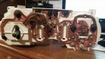
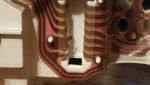
My tachometer and 4X4 light went out in my cluster, so I removed it and found a couple of damaged circuit board traces kinda messed up... can someone tell me what these 2 tracks goto? Right to the right of the speedometer cable, there is a plug. Bottom left you can see the tracks kinked. Can someone tell me what those are for?

Also, where a bulb is supposed to go for the Check Engine light is blocked so you can not install a blub.. Any reason for that?
And also it looks to have NEVER had a Check Oil light bulb in it's socket.

Thanks!
Charles
 

Attachments

Last edited:


85_Ranger4x4

Forum Staff Member
TRS Event Staff
TRS Forum Moderator
Article Contributor
V8 Engine Swap
OTOTM Winner
TRS Banner 2010-2011
TRS 20th Anniversary
VAGABOND
TRS Event Participant
Joined
Aug 7, 2007
Messages
32,312
Reaction score
17,757
Points
113
Location
SW Iowa
Vehicle Year
1985
Make / Model
Ford
Engine Type
V8
Engine Size
5.0
Transmission
Manual
I will say I ran into that with mine and after fighting and fighting I ended up swapping the speedo into a different cluster.

I tried supergluing them down, nothing would work. Kind of a cruddy design IMO.

The tach side connector has been charted but I haven't seen anyone do the speedo side connector. You might be able to trace them and interpolate what they do though.
 

adsm08

Senior Master Grease Monkey
Supporting Member
Article Contributor
Ford Technician
TRS 20th Anniversary
Joined
Sep 20, 2009
Messages
34,623
Reaction score
3,613
Points
113
Location
Dillsburg PA
Vehicle Year
1987
Make / Model
Ford
Engine Type
4.0 V6
Engine Size
4.0
Transmission
Manual
2WD / 4WD
4WD
Tire Size
31X10.50X15
I will say I ran into that with mine and after fighting and fighting I ended up swapping the speedo into a different cluster.

I tried supergluing them down, nothing would work. Kind of a cruddy design IMO.

The tach side connector has been charted but I haven't seen anyone do the speedo side connector. You might be able to trace them and interpolate what they do though.
I have traced them both out, but didn't take good notes on it.


It is hard to see in this picture where they run. The upper two obviously just jumper around to each other. I think the lower one goes to the lights, but it is hard to see. The easy way to tell is to bust out an ohm meter and see what that sucker has continuity to.
 
Last edited:

The Slider

Member
Joined
Oct 8, 2007
Messages
258
Reaction score
1
Points
18
Age
53
Location
Castroville, Texas
Vehicle Year
1986
1972
Make / Model
Ford
Transmission
Automatic
The small one (Worst one) goes to the 2 screws to the right and left of the gray plug w/ the resister in it, below the tachometer. The other way it goes to the silver box (Diode? Relay?) (Top Right hand corner of the speedometer cable) looks like a snake head. What is that for?

Thanks again!
Chaz
BTW.. How would you test the Tachometer for 86? Dark Green/Yellow Wire? Start the engine and put a 12v test light it?
 

adsm08

Senior Master Grease Monkey
Supporting Member
Article Contributor
Ford Technician
TRS 20th Anniversary
Joined
Sep 20, 2009
Messages
34,623
Reaction score
3,613
Points
113
Location
Dillsburg PA
Vehicle Year
1987
Make / Model
Ford
Engine Type
4.0 V6
Engine Size
4.0
Transmission
Manual
2WD / 4WD
4WD
Tire Size
31X10.50X15
The silver box above the speedo plug is the IPVR (instrument panel voltage regulator). It helps keep voltage to the gauges from spiking so that they don't fluctuate. Those gauges run off 5V not 12.

The resistor in the bottom of the tach side is for the charging indicator system. It is there so that if the bulb burns out the alternator can still get power to turn on.
 

The Slider

Member
Joined
Oct 8, 2007
Messages
258
Reaction score
1
Points
18
Age
53
Location
Castroville, Texas
Vehicle Year
1986
1972
Make / Model
Ford
Transmission
Automatic
I have traced them both out, but didn't take good notes on it.


It is hard to see in this picture where they run. The upper two obviously just jumper around to each other. I think the lower one goes to the lights, but it is hard to see. The easy way to tell is to bust out an ohm meter and see what that sucker has continuity to.
I went to look at the plug that goes in those bad tracks... the REALLY bad one has no wire that goes to it. (maybe the track got mangled at one time it got removed?) and the one above it that loops around has 2 brown wires connected together. So I'm going to say I am OK with the C/B I have on the cluster. My Tachometer however (which died) had a dark brown spot around 2 resisters and a jumper wire... So i ordered a new Tachometer..
 

Sponsored Ad


Sponsored Ad

Staff online

Member & Vendor Upgrades

For a small yearly donation, you can support this forum and receive a 'Supporting Member' banner, or become a 'Supporting Vendor' and promote your products here. Click the banner to find out how.

Truck of The Month


Shran
April Truck of The Month

Recently Featured

Want to see your truck here? Share your photos and details in the forum.

Follow TRS On Instagram

TRS Events

25th Anniversary Sponsors

Check Out The TRS Store


Sponsored Ad


Sponsored Ad

Sponsored Ad


Amazon Deals

Top