The other gauges are not working?
The fuel gauge uses 5volt pulse power, so not sure you would see any power at the switch.
Fuel pump power is only on for 2 seconds when key is turned on.
The senders in the tank are the ground connection for the gauge, out of the selector switch there should be a dark blue/yellow wire and a yellow/light blue wire, these are the sending unit wires.
And there will be a yellow/white wire, that wire goes to the gauge.
To test the gauge:
With key on disconnect the yellow/white wire, gauge should go to below Empty.
Now Ground the yellow/white wire, gauge should go to above Full
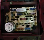
If this happens gauge and power to gauge is OK, if it doesn't happen then power to gauge or anti-slosh module behind gauge is not working.
Pre-89 Fords use gauges and sending units that use 73-10 Ohms range.
So sender will show 73ohms when tank is empty, 10ohms when tank is full.
Use an OHM meter to test the dark blue/yellow wire and the yellow/light blue wire at the switch.
So one probe from meter to dark blue/yellow wire and the other probe wire to a good ground, repeat for second sender wire.
If you are reading no connection then ground wire for the senders may be disconnected or corroded, they should share a common ground, so if one sender reads no connection it might be bad, but look for it's Black Ground wire.
If OHM meter shows between 10 and 73 ohms then senders are most likely OK, but you can siphon or add gas to each tank to make sure OHMs change a bit.
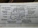
The path of the fuel gauge is:
Voltage regulator---------Fuel gauge/anti-slosh----------(switch)-------sender----Ground