A1 CHECK THE BATTERY
Check the battery condition and charge; refer to Section 414-00.
Is the battery OK?
Yes
GO to A2.
No
CHARGE or REPLACE the battery as required. TEST the system for normal operation.
A2 CHECK THE BATTERY GROUND CABLE
Measure the voltage between the positive battery post and the battery ground cable connection at the cylinder block (6010) or the starter motor mounting stud bolt (for the 4.0L engine).
Is the voltage reading greater than 10 volts?
Yes
GO to A3.
No
REPLACE the battery ground cable (14301). TEST the system for normal operation.
A3 CHECK THE STARTER MOTOR GROUND
Measure the voltage between the battery positive post and the starter motor case.
Is the voltage reading greater than 10 volts?
Yes
GO to A4.
No
CLEAN the starter motor mounting flange and make sure the starter motor is properly mounted. TEST the system for normal operation.
A4 CHECK THE POWER SUPPLY TO THE STARTER MOTOR
Measure the voltage at the starter motor B terminal.
Is the voltage reading greater than 10 volts?
Yes
GO to A5.
No
REPLACE the positive battery cable. TEST the system for normal operation.
A5 CHECK THE STARTER MOTOR B-TERMINAL
Connect one end of a jumper wire to the B terminal of the starter motor and momentarily connect the other end to the starter solenoid S terminal.
Does the starter motor engage and the engine crank?
Yes
GO to A6.
No
REPLACE the starter motor. TEST the system for normal operation.
A6 CHECK START INPUT TO THE STARTER MOTOR
Stater S Connector
Hold the ignition switch to the START position.
Measure the voltage at the starter motor solenoid S terminal.
Is the voltage reading greater than 10 volts?
Yes
CLEAN the starter solenoid S terminal and connector. CHECK the wiring and the starter motor for a loose or intermittent connection. TEST the system for normal operation.
No
GO to A7.
A7 CHECK THE START INPUT TO THE STARTER RELAY
Starter Relay
Hold the ignition switch in the START position.
Measure the voltage at the starter relay connector Pin 86, Circuit 1093 (T/R).
Is the voltage reading B+?
Yes
GO to A8.
No
GO to A12.
A8 CHECK THE BATTERY SUPPLY TO THE STARTER RELAY
Measure the voltage at the starter relay connector Pin 30, Circuit 37 (Y).
Is the voltage reading B+?
Yes
GO to A9.
No
REPAIR the open in Circuit 37 (Y). TEST the system for normal operation.
A9 CHECK THE STARTER RELAY GROUND
Measure the resistance between the starter relay connector Pin 85, Circuit 57 (BK) and ground.
Is the resistance reading 5 ohms or less?
Yes
GO to A10.
No
REPAIR Circuit 57 (BK) for an open. TEST the system for normal operation.
A10 CHECK CIRCUIT 113 (Y/LB) FOR A SHORT TO GROUND
Starter Solenoid S Connector
Measure the resistance between the starter relay connector Pin 87, Circuit 113 (Y/LB) and ground.
Is the resistance reading 10,000 ohms or less?
Yes
REPAIR Circuit 113 (Y/LB) for a short to ground. TEST the system for normal operation.
No
GO to A11.
A11 CHECK CIRCUIT 113 (Y/LB) FOR AN OPEN
Measure the resistance of Circuit 113 (Y/LB) between the starter relay connector Pin 87 and the starter solenoid S Connector.
Is the resistance reading 5 ohms or less?
Yes
REPLACE the starter relay. TEST the system for normal operation.
No
REPAIR circuit 113 (Y/LB) for an open. TEST the system for normal operation.
A12 CHECK THE START INPUT TO THE CLUTCH PEDAL POSITION SWITCH (CPP)
CPP Switch C206
Make sure the anti-theft system is disabled (if equipped); refer to Section 419-01.
Hold the ignition switch to the START position.
Measure the voltage at the CPP switch or jumper connector Pin C206-6, Circuit 33 (W/PK).
Is voltage reading B+?
Yes
GO to A23.
No
GO to A13.
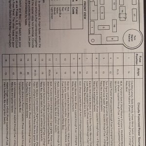
A13 CHECK FUSE 24 (7.5A)
Fuse Junction Panel Fuse 24 (7.5A)
Fuse Junction Panel Fuse 24 (7.5A)
Is Fuse 24 (7.5A) OK?
Yes
GO to A14 .
No
GO to A19.
A14 CHECK THE INPUT TO FUSE 24 (7.5A)
Hold the ignition switch to the START position.
Measure the voltage at the input cavity of Fuse 24 (7.5A).
Is the voltage reading B+?
Yes
If equipped with anti-theft system GO to A15 . If not equipped with anti-theft, REPAIR Circuit 33 (W/PK) for an open. TEST the system for normal operation.
No
GO to A26.
A15 CHECK FOR AN ENABLED THEFT RELAY
Anti-Theft Relay
Make sure the anti-theft system is disabled; refer to Section 419-01.
Measure the resistance between the anti-theft relay connector Pin 1, Circuit 342 (LG/P) and ground.
Is the resistance reading 50 ohms or less?
Yes
GO to A16.
No
GO to A17.
A16 CHECK FOR A SHORTED REMOTE ANTI-THEFT PERSONALITY (RAP) MODULE
RAP 409
Measure the resistance between the anti-theft relay connector Pin 1, Circuit 342 (LG/P) and ground.
Is the resistance reading 50 ohms or less?
Yes
REPAIR Circuit 342 (LG/P) for a short to ground. TEST the system for normal operation.
No
REPLACE the remote anti-theft personality module. TEST the system for normal operation.
A17 CHECK THE START INPUT TO THE ANTI-THEFT RELAY
Fuse 24 (7.5A)
Hold the ignition switch in the START position.
Measure the voltage at the anti-theft relay connector Pins 2 and 3, Circuit 32 (R/LB).
Is the voltage reading B+?
Yes
GO to A18.
No
REPAIR circuit 32 (R/LB) for an open. TEST the system for normal operation.
A18 CHECK CIRCUIT 33 (W/PK) FOR AN OPEN
Measure the resistance of Circuit 33 (W/PK) between the anti-theft relay connector Pin 4 and the CPP switch or jumper connector Pin C206-6.
Is the resistance reading 5 ohms or less?
Yes
REPAIR Circuit 33 (W/PK) for an open. TEST the system for normal operation.
No
REPLACE the anti-theft relay. TEST the system for normal operation.
A19 CHECK THE CPP INPUT FOR A SHORT TO GROUND
Measure the resistance between the CPP switch or jumper connector Pin C206-6, Circuit 33 (W/PK) and ground.
Is the resistance reading 10,000 ohms or less?
Yes
REPAIR Circuit 33 (W/PK) or Circuit 32 (R/LB) for a short to ground. TEST the system for normal operation.
No
GO to A20.
A20 CHECK CPP OUTPUT FOR A SHORT TO GROUND
Starter Relay
Measure the resistance between the CPP switch or jumper connector Pin 206-5, Circuit 329 (PK) and ground.
Is the resistance reading 10,000 ohms or less?
Yes
For manual transmission, REPAIR Circuit 329 (PK) or Circuit 1093 (T/R) for a short to ground. For automatic transmission GO to A21 .
No
REPLACE Fuse 24 (7.5A). TEST the system for normal operation. If Fuse 24 opens again, CHECK the starting system for an intermittent short to ground.
A21 CHECK FOR A SHORTED DIGITAL TRANSMISSION RANGE (TR) SENSOR
Digital TR Sensor C1005
Measure the resistance between the CPP switch or jumper connector Pin C206-5, Circuit 329 (PK) and ground.
Is the resistance greater than 10,000 ohms or less?
Yes
REPAIR Circuit 329 (PK) for short to ground. TEST the system for normal operation.
No
GO to A22.
A22 CHECK CIRCUIT 1093 (T/R) FOR A SHORT TO GROUND
Measure the resistance between digital TR sensor connector Pin C1005-10, Circuit 1093 (T/R) and ground.
Is the resistance reading greater than 10,000 ohms or less?
Yes
REPAIR Circuit 1093 (T/R) for a short to ground. TEST the system for normal operation.
No
CHECK the digital TR sensor adjustment; refer to Section 307-01A (4R44E) or Section 307-01B (5R55E). If the digital TR sensor is not adjusted properly, REPLACE the digital TR sensor. TEST the system for normal operation.
A23 CHECK CPP OUTPUT FOR AN OPEN
Starter Relay
Measure the resistance between the CPP connector Pin C206-5, Circuit 329 (PK) and the starter relay connector Pin 86, Circuit 1093 (T/R).
Is the resistance reading 5 ohms or less?
Yes
REPLACE the clutch pedal position switch or jumper. TEST the system for normal operation.
No
For manual transmission, REPAIR Circuit 329 (PK) or Circuit 1093 (T/R) for an open. TEST the system for normal operation. For automatic transmission, GO to A24 .
A24 CHECK CIRCUIT 329 (PK) FOR AN OPEN
Digital TR Sensor C1005
Measure the resistance of Circuit 329 (PK) between the CPP connector Pin C206-5 and the digital TR sensor connector Pin C1005-12.
Is the resistance reading 5 ohms or less?
Yes
GO to A25.
No
REPAIR Circuit 329 (PK) for an open. TEST the system for normal operation.
A25 CHECK CIRCUIT 1093 (T/R) FOR AN OPEN
Measure the resistance of Circuit 1093 (T/R) between the starter relay connector Pin 86 and the digital TR sensor connector Pin C1005-10.
Is the resistance reading 5 ohms or less?
Yes
CHECK the digital TR sensor adjustment; refer to Section 307-01A (4R44E) or Section 307-01B (5R55E). If the digital TR sensor is adjusted properly, REPLACE the digital TR sensor. TEST the system for normal operation.
No
REPAIR Circuit 1093 (T/R) for an open. TEST the system for normal operation.
A26 CHECK THE SUPPLY TO THE IGNITION SWITCH
Ignition Switch C213
Measure the voltage at the ignition switch connector Pin C213-B4, Circuit 37 (Y).
Is the voltage reading greater than 10 volts?
Yes
GO to A27.
No
REPAIR Circuit 37 (Y) for an open. TEST the system for normal operation.
A27 CHECK CIRCUIT 32 (R/LB) FOR AN OPEN
Measure the resistance of Circuit 32 (R/LB) between the ignition switch connector Pin C213-STA and the input cavity of Fuse 24 (7.5A).
Is the resistance reading 5 ohms or less?
Yes
REPLACE the ignition switch; refer to Section 211-05. TEST the system for normal operation.
No
REPAIR Circuit 32 (R/LB) for an open. TEST the system for normal operation.


